Barton BMC31 QTLFO
-
 Mar 24, 2023
- edited: Nov 14, 2023
My synth rack needs more LFO’s so I’ve been looking around the internet for interesting designs lately. I ran into the BMC31 Quad Trapezoidal LFO on the Barton Musical Circuits website and after reading the documentation I knew I had to build one. It’s a really interesting module and a rather simple circuit so it’s a bit weird that it isn’t more popular.
It has 4 stages kind of like an ADSR and you can adjust their lengths with 4 potentiometers. During stage 1 the voltage of output 1 rises from -5V to 5V, during stage 2 it stays at 5V, during stage 3 it falls from 5V to -5V and during stage 4 it stays at -5V. The other 3 outputs do the same thing but offset by 1 stage from eachother.

Here’s Barton’s video on Youtube showing it off
I think it will be useful paired with some VCAs fading in and out sounds in ambient patches.
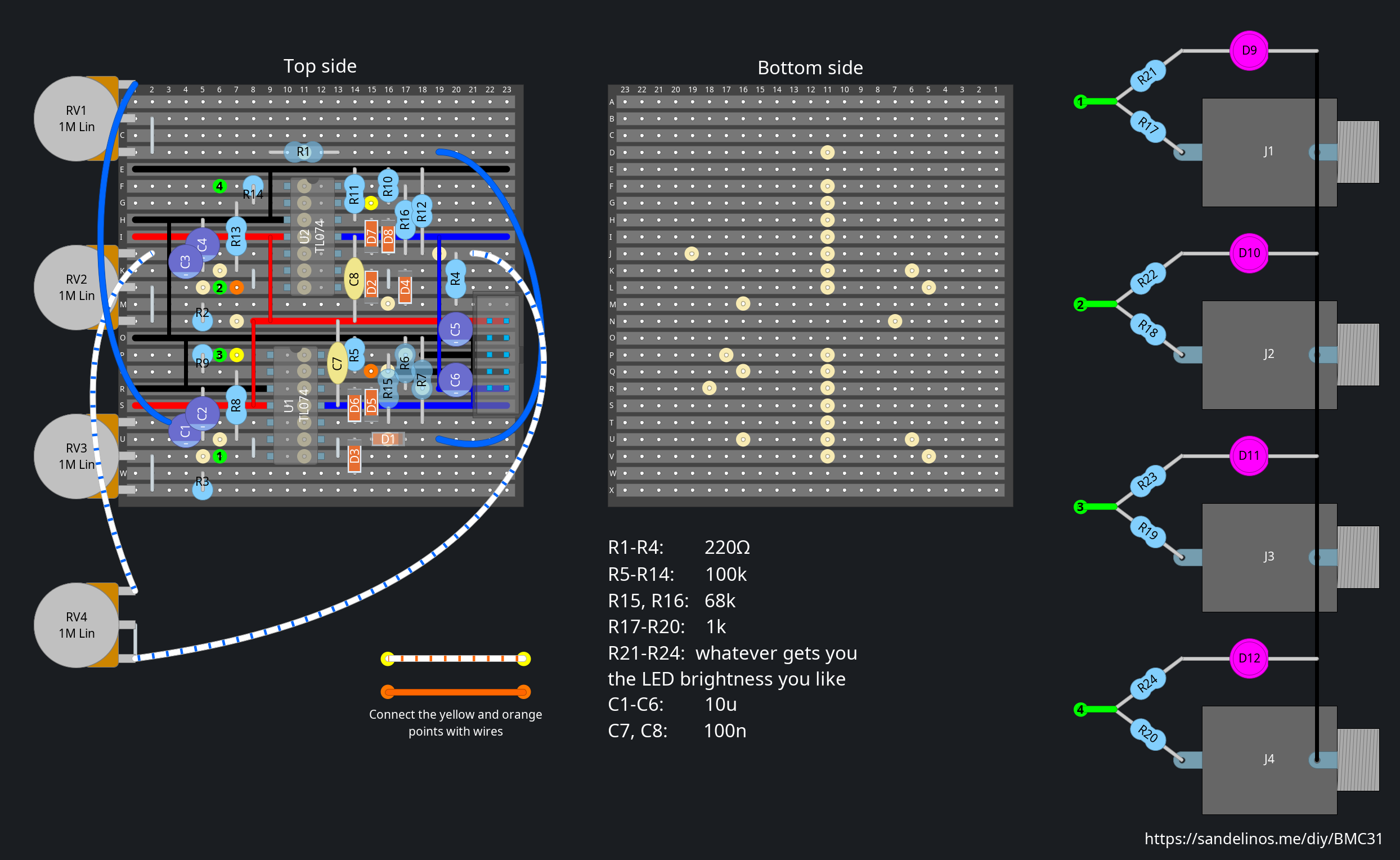
Here’s the stripboard layout I came up with. You can download the DIYLC project file below.
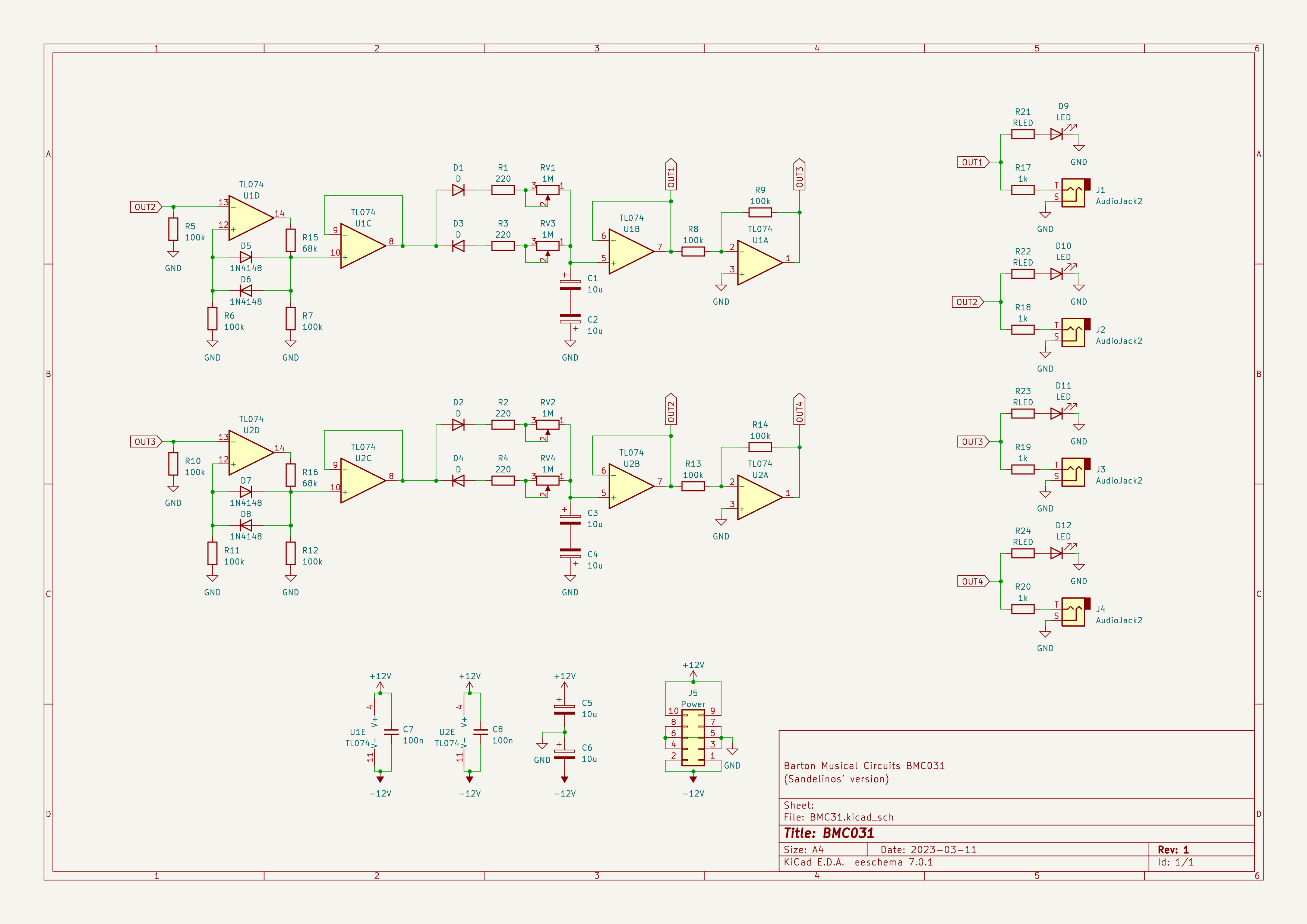
Here’s the schematic. You can download it below.
If stripboard isn’t your thing you can buy the original PCB and 8HP front panel from Barton for $8 each.
In Barton’s original circuit turning the pots clockwise decreases the length of the stage so they act like “speed” knobs. In my version I reversed the pots so they act like “length” knobs which makes more sense to me in this context. I also got rid of the 10Ω resistors in series with the power input to save space and replaced the 10nF decoupling caps with 100nF ones.
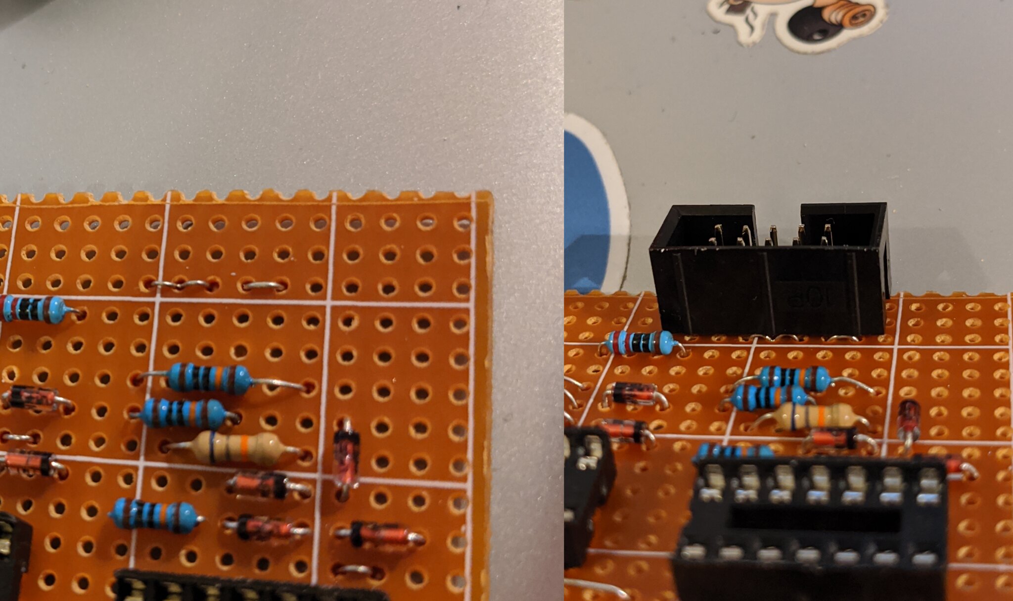
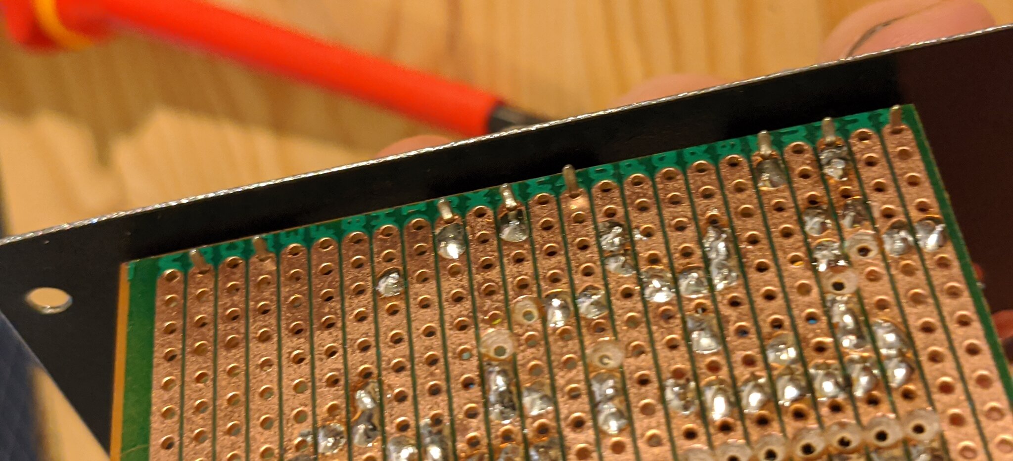
The shrouded power header covers the row of holes next to it so these jumpers need to be soldered on before the power header. (And you should use a shrouded header because there is no reverse-polarity protection on the board)
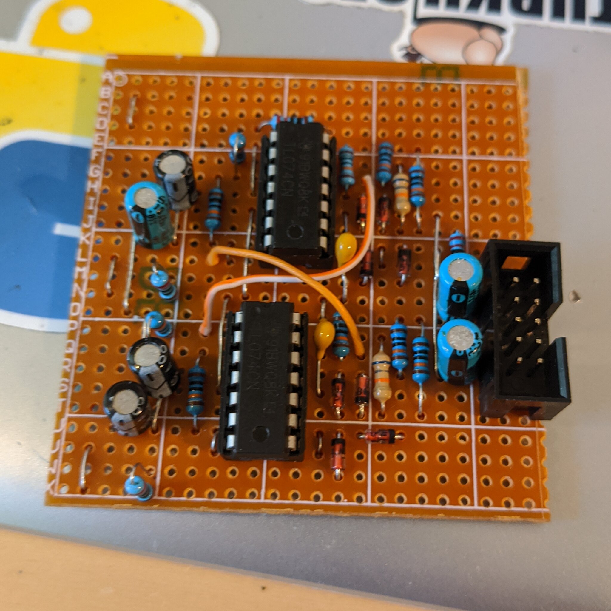
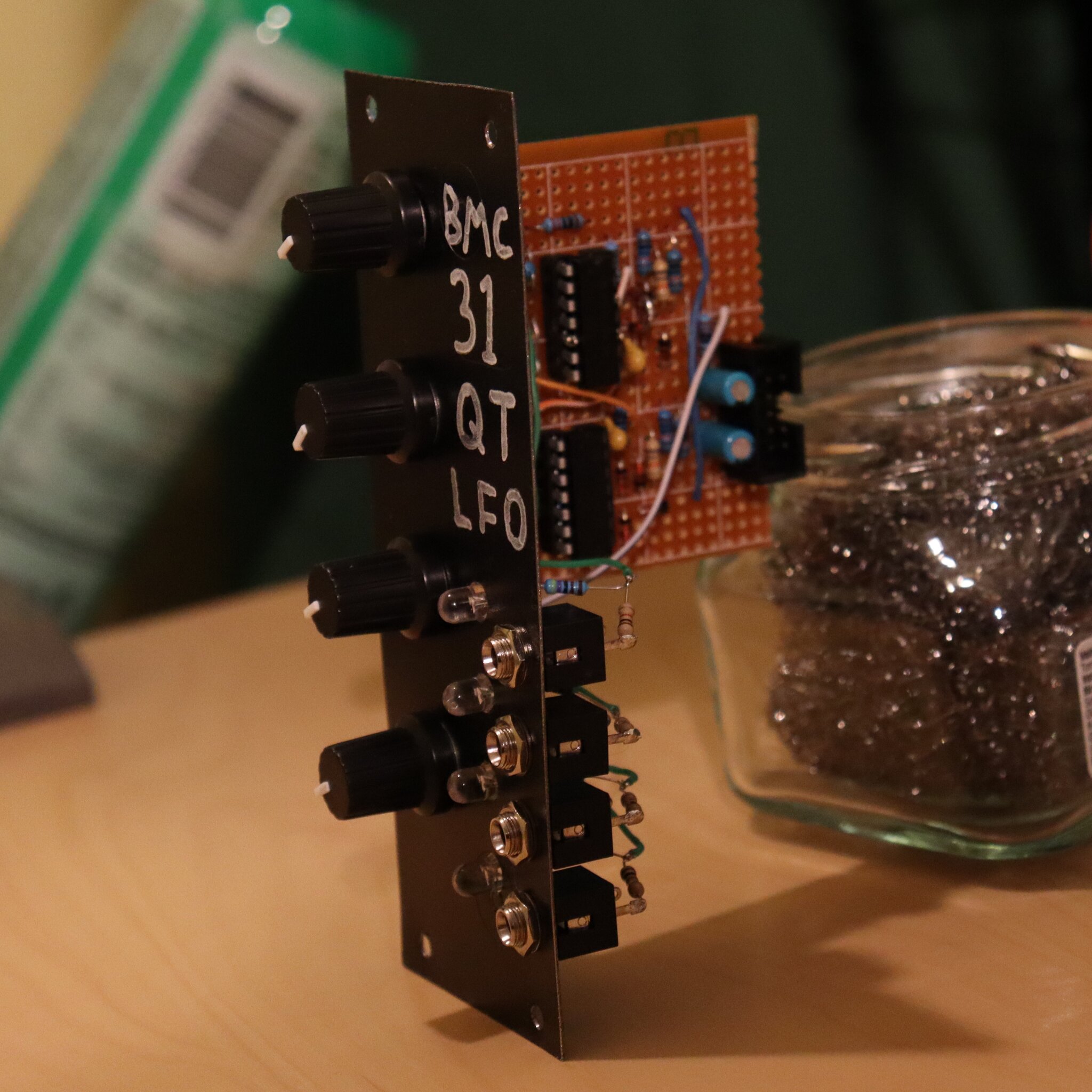
When building the module I ran out of 10μF capacitors so I salvaged the teal ones you see here from an old stereo receiver. They look really pretty but generally it’s not a good idea to use salvaged electrolytic caps if you can avoid it.
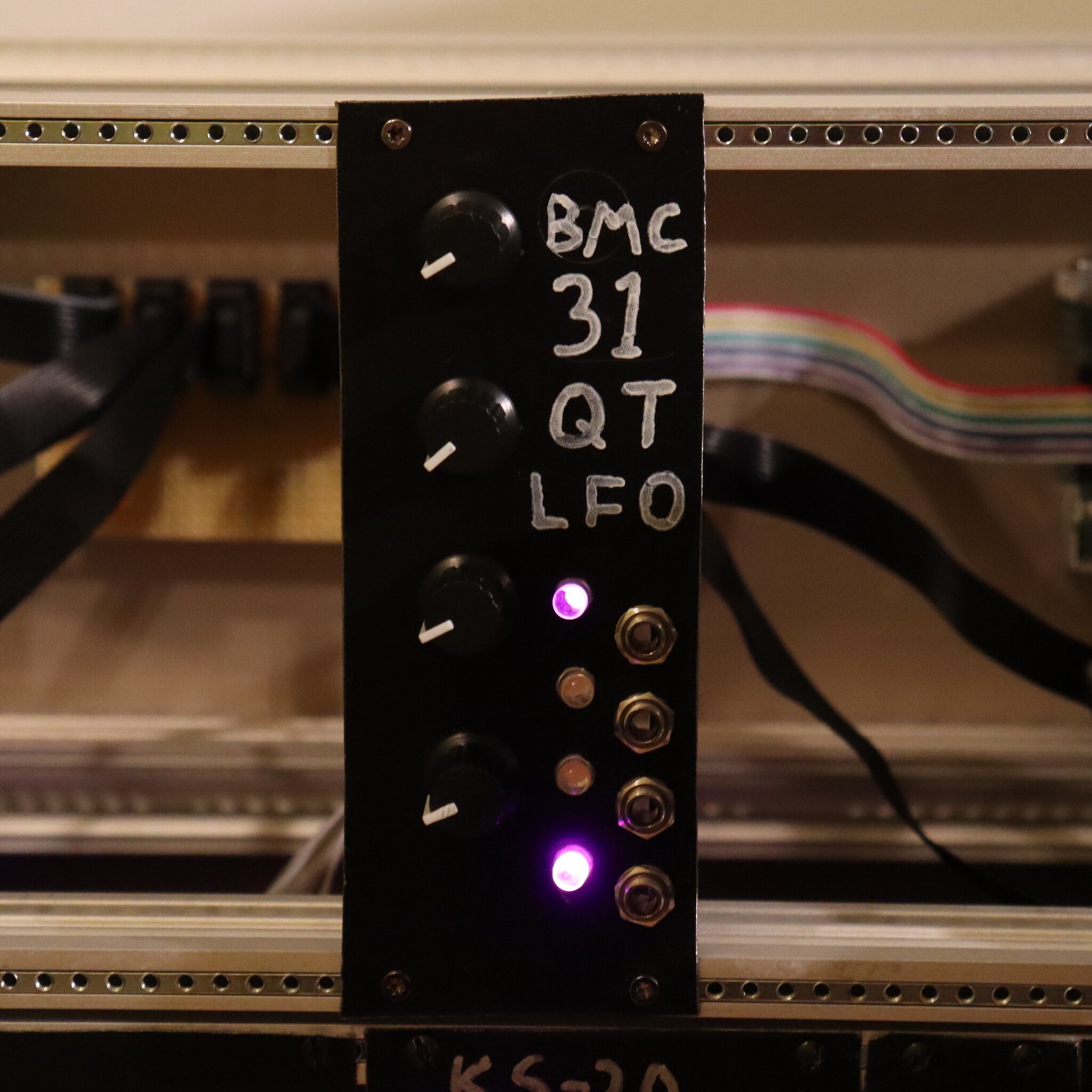
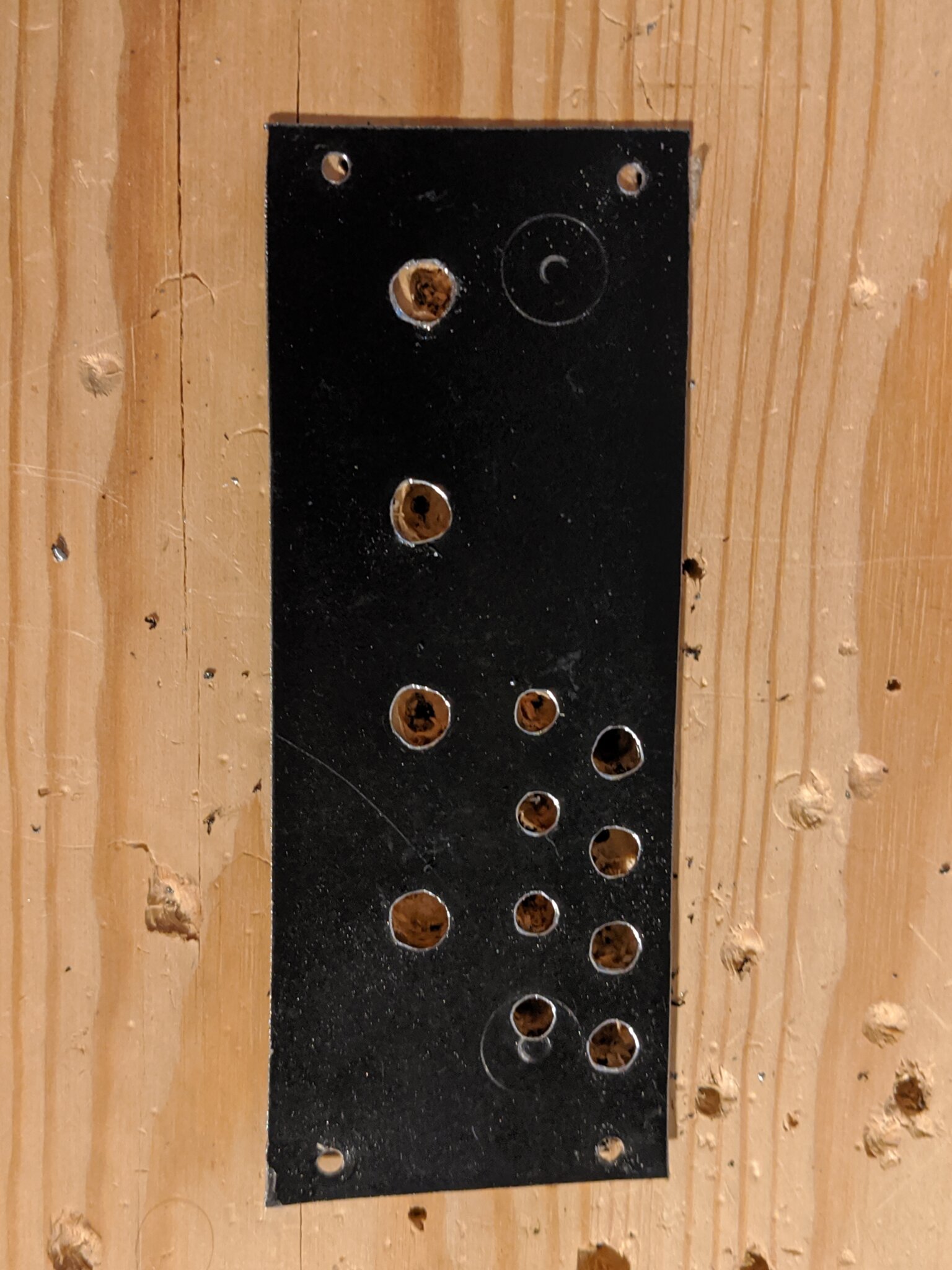
Here’s the front panel I made. It’s 10HP wide. You can download the template for it below.
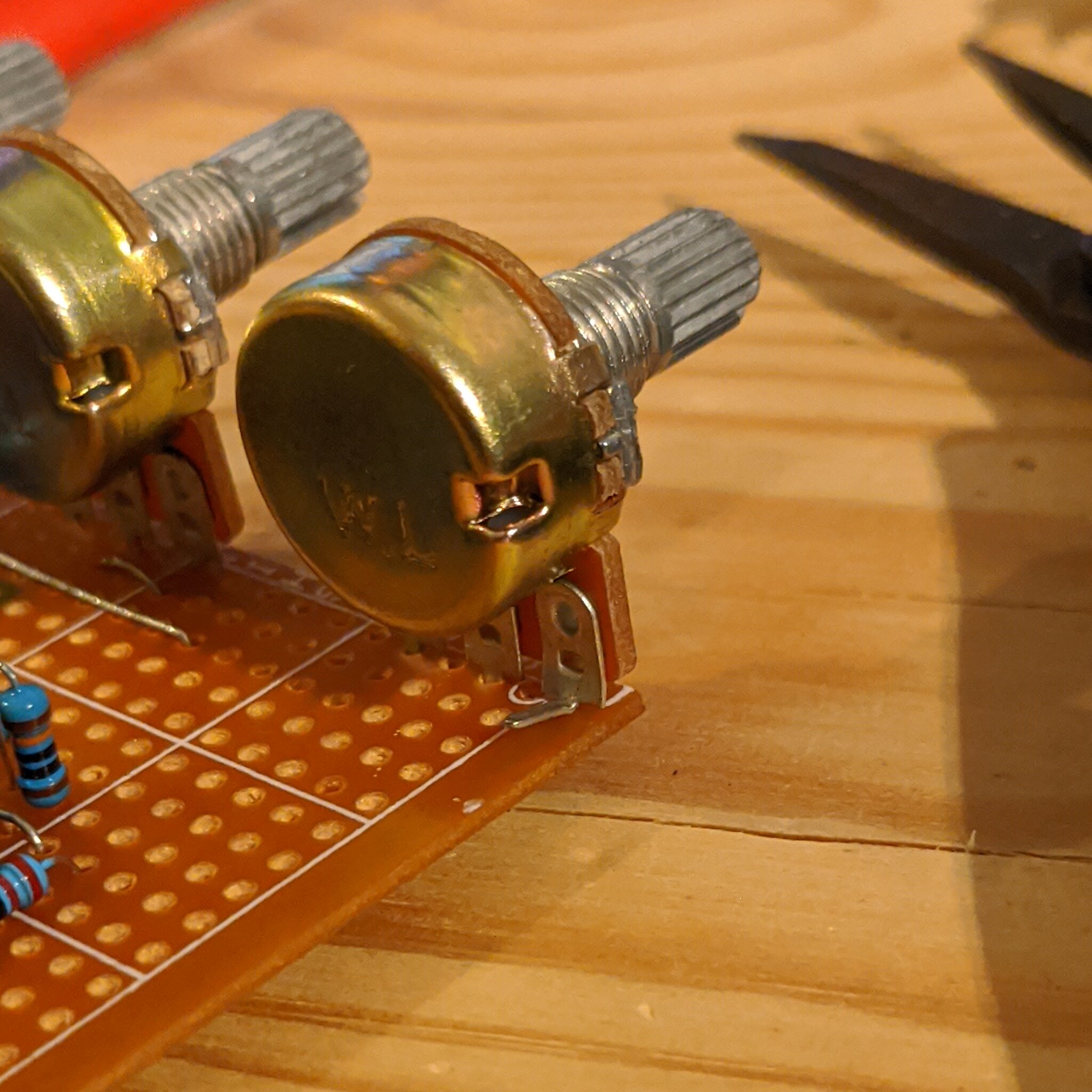
24-row stripboards are 1 row too short for the three pots, so leg 1 of RV1 needs to be bent backwards and the jumper wire soldered straight on to it.
In order to avoid stress to the stripboard the pots should first be put on the board but not soldered in, then screwed on to the front panel and then soldered in.
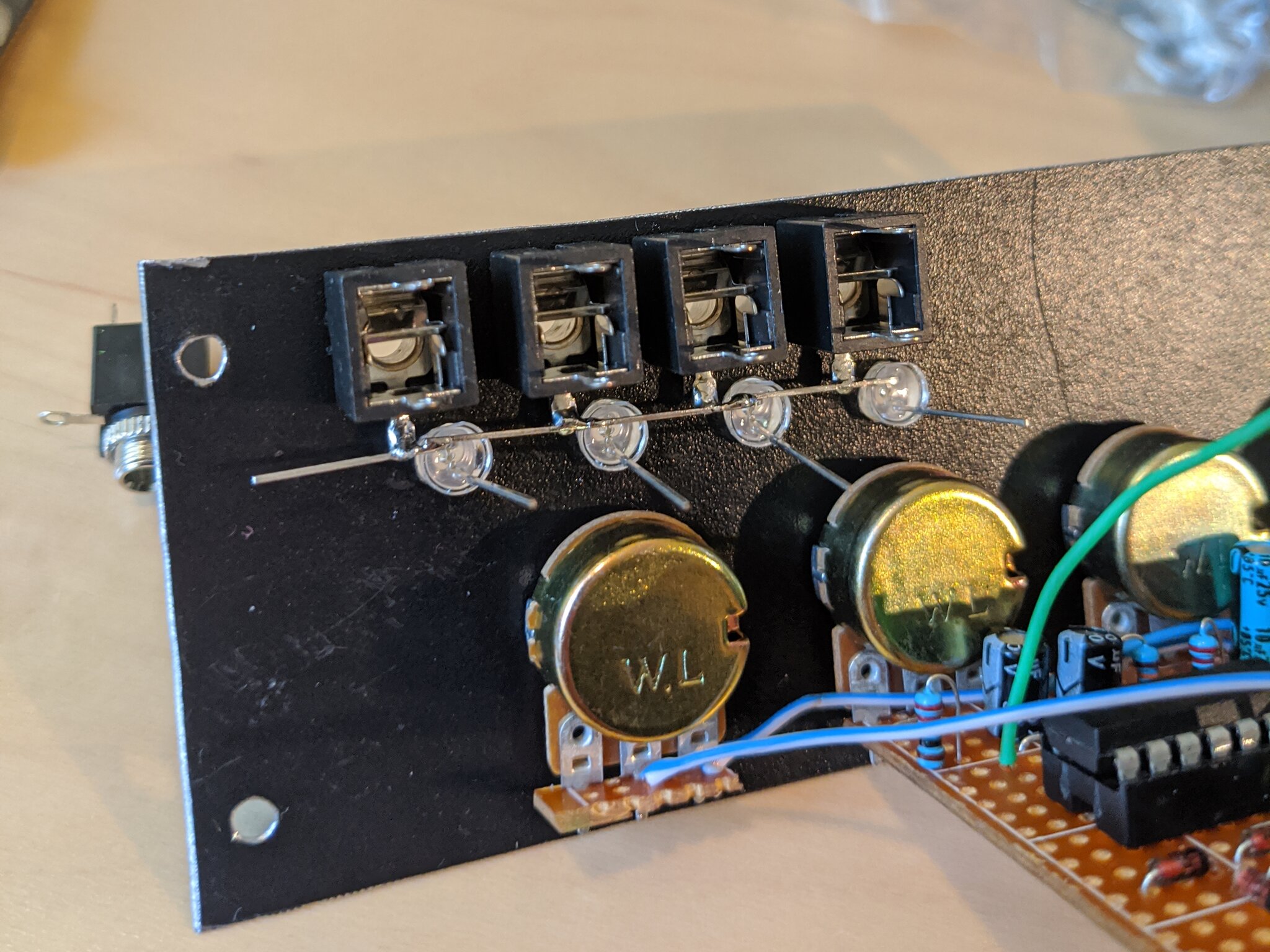
To mount the output jacks and LEDs I first screwed the jacks on to the front panel, put the LEDs in their holes and then soldered all the grounds together by using the cathode legs of the LEDs.
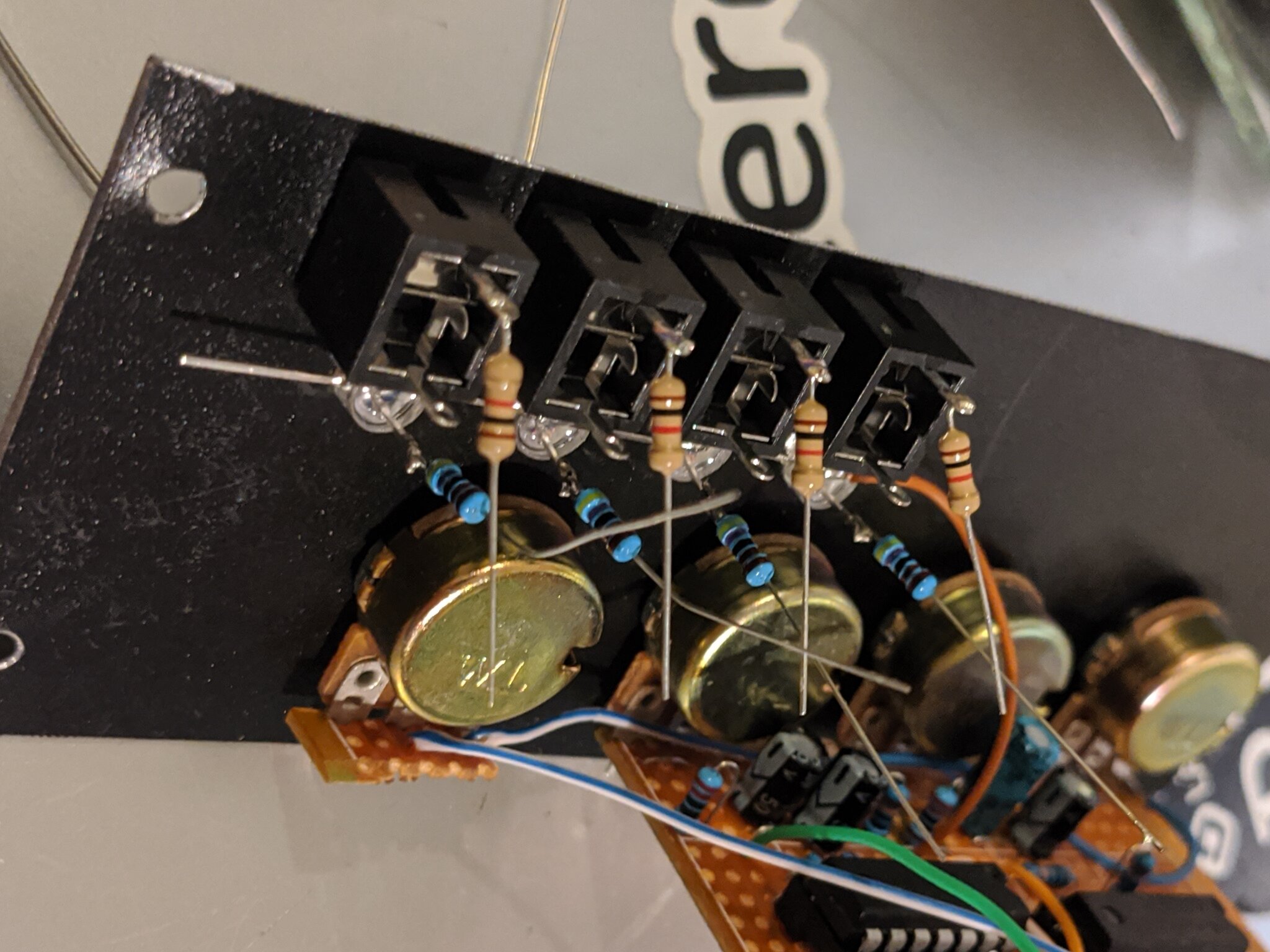
Then I soldered on the current limiting resistors for the outputs and the LEDs. I chose 4.7k resistors for the LEDs by trial and error to get the brightness I liked.
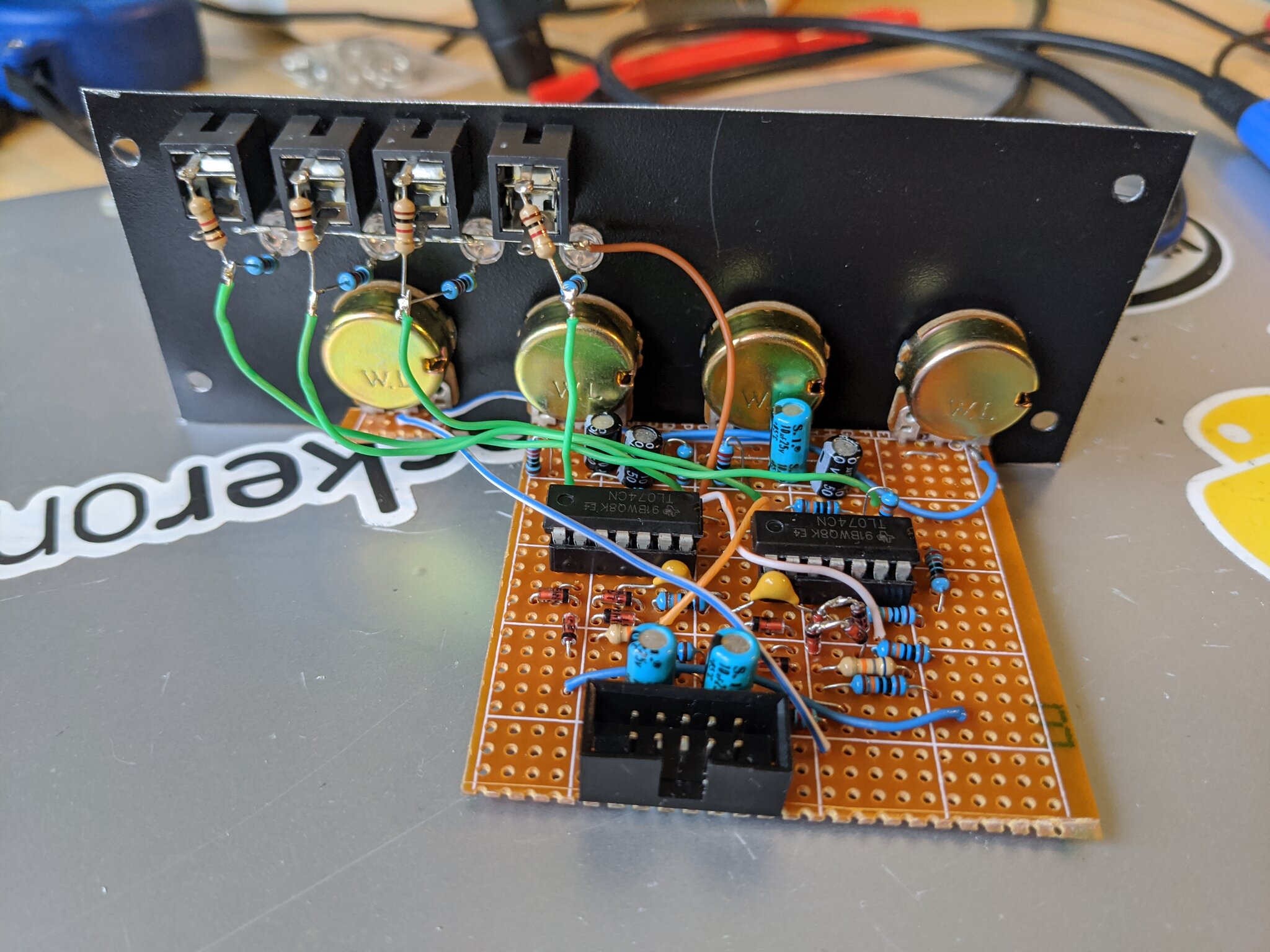
Then I twisted the resistor legs together and soldered them to the board with wires and that’s the module done.
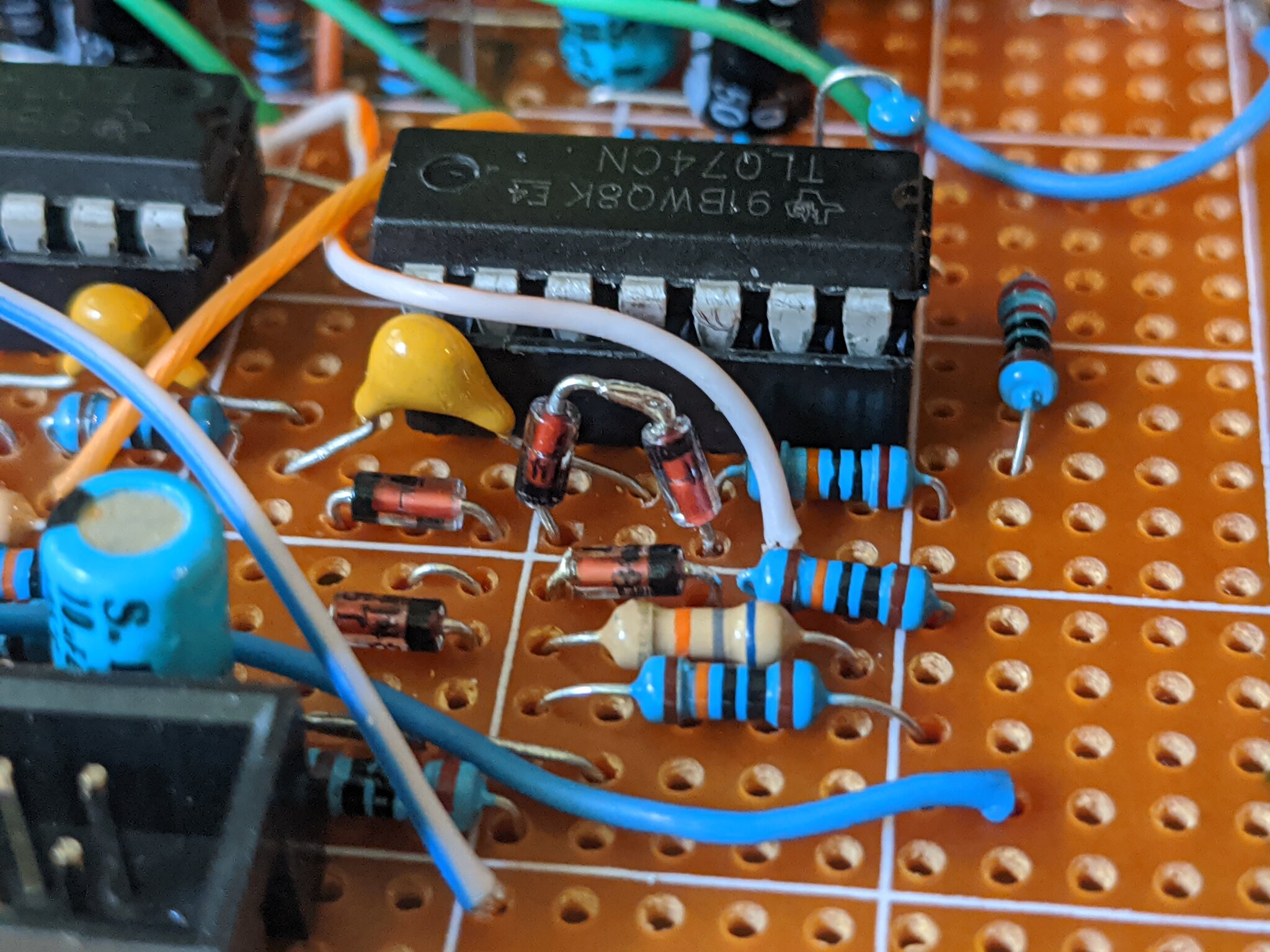
After finishing the build and plugging in the module for the first time it would get stuck at the top of the rising stage of output 1 even with RV1 turned all the way down. I think it was caused by tolerance differences between D1 and D7 so I compensated by replacing D7 with 2 diodes in series to bring the voltage at the non-inverting input of U2D a little higher and the module now works.
Below are photos of the finished module.