Adding a redundant power supply to a MikroTik switch
-
 Jan 28, 2023

Having redundant power supplies is a very useful feature to have in network equipment so I modified this cheap MikroTik network switch to add one.
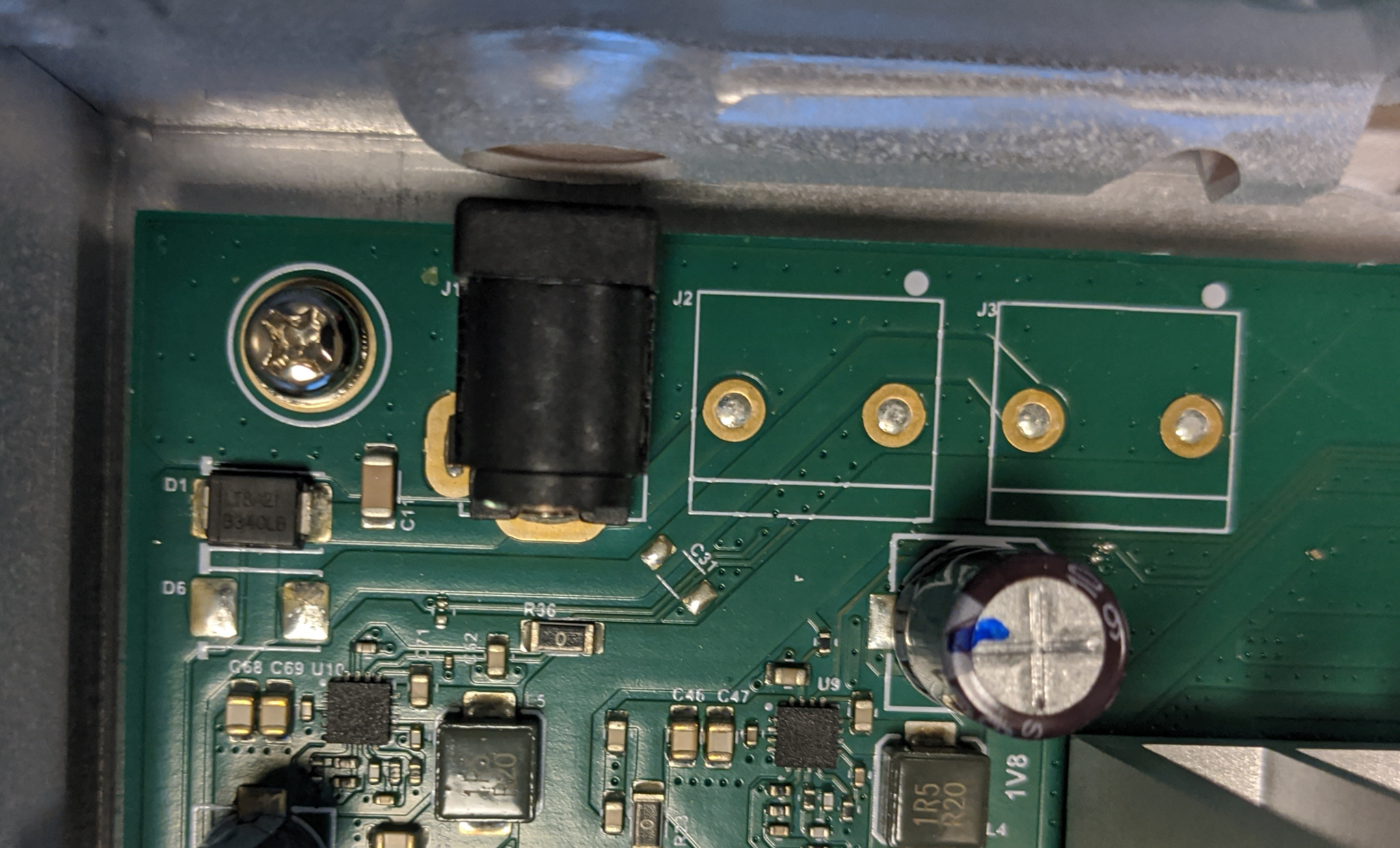
When you open up the switch and take a look at the motherboard you see that there are 2 unpopulated spots for some kind of connectors (J2, J3) next to the DC power input socket J1. This is most likely because the same PCBs are also used in some other models that have built-in redundant power supplies instead of an external DC power brick. The left one is in parallel with the DC power input socket. The positive pin connects to the anode of a B340LB schottky diode (D1), through which it supplies power to the switch. Since the built-in power jack connects to the rest of the circuit through a diode, all we need to do to add more power inputs is to connect more power connectors through diodes. I could just solder a diode to the cathode of D1 and connect it to a DC jack with a wire, but since we have the unpopulated spots for J3 and D6 on the board I’ll use those for a cleaner end result.
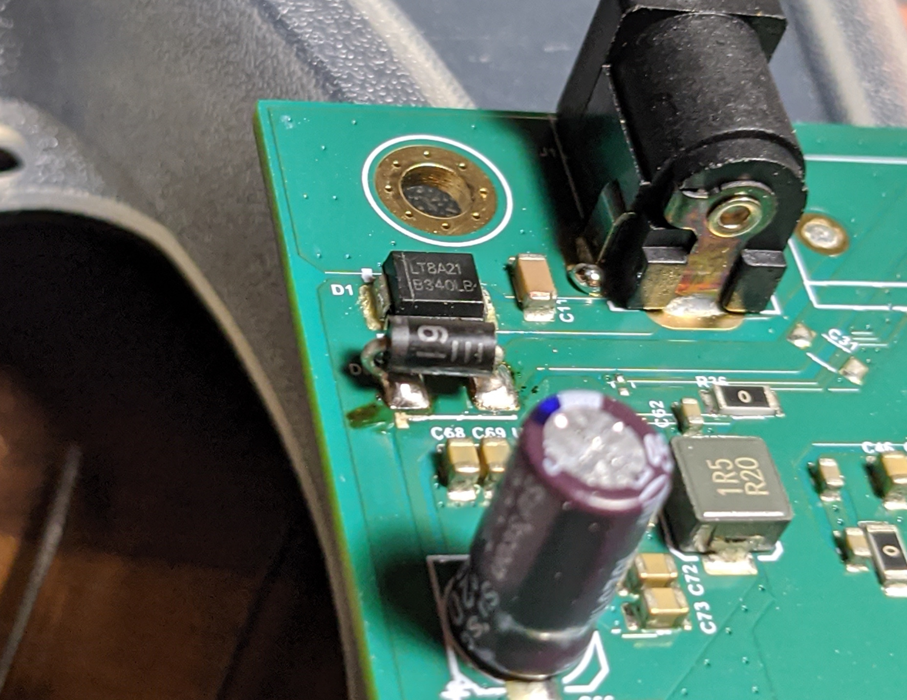
I don’t have any B340LB lying around so I soldered a 1N5819 on the D6 pads. I had to do a bit of acrobatics with the legs since I was soldering a through-hole diode on the pads of an SMT one.
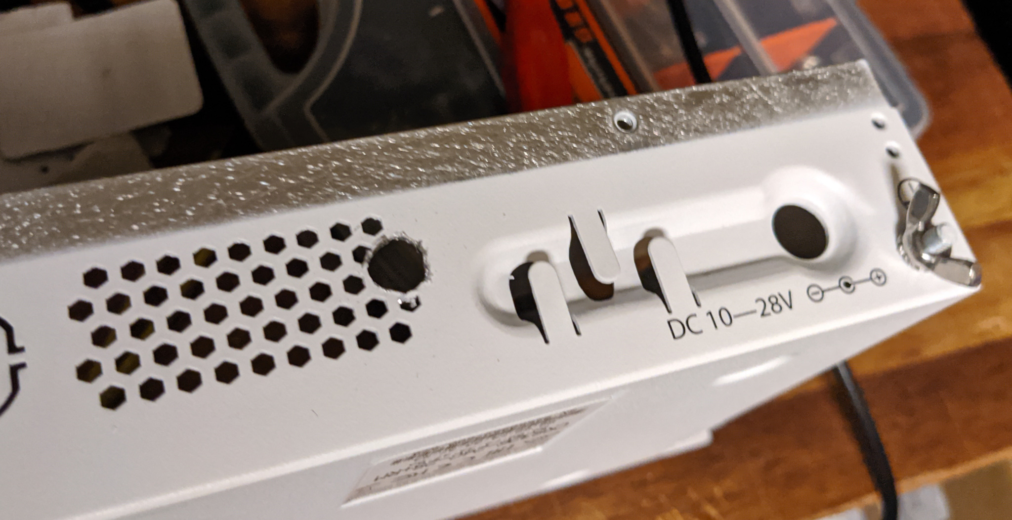
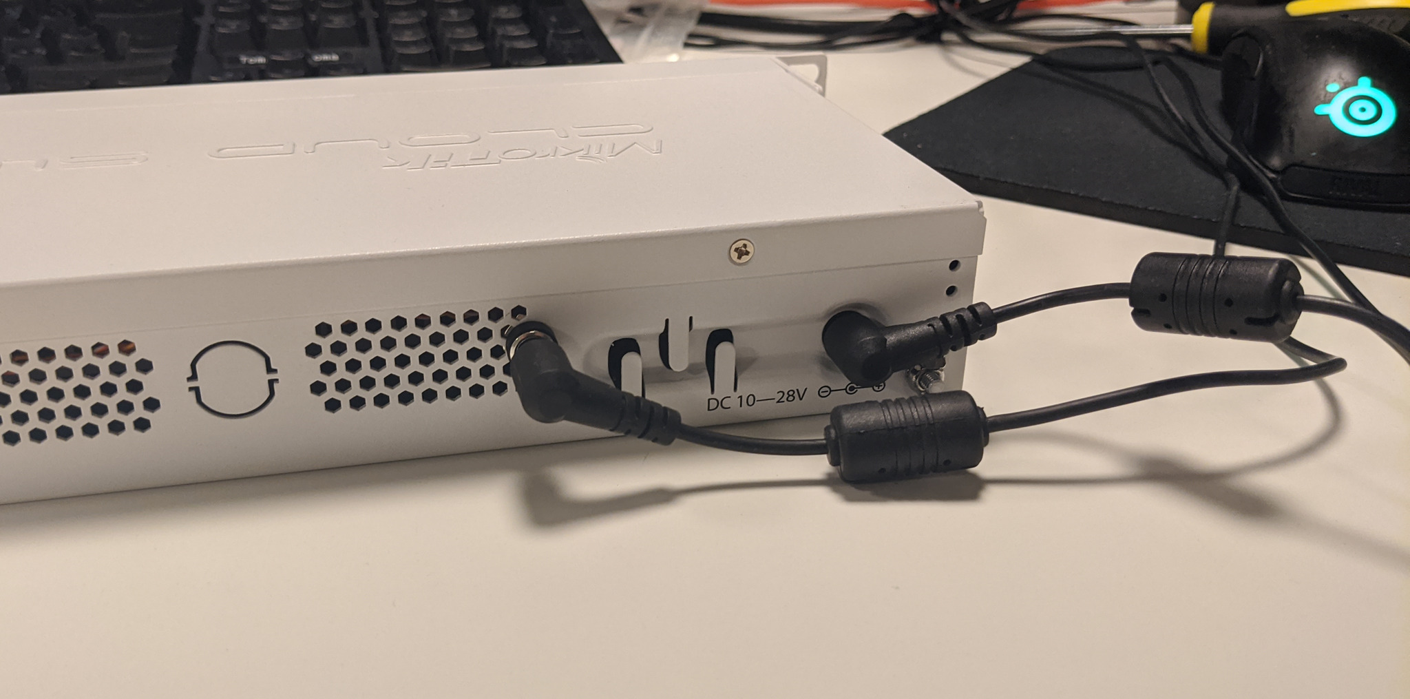
I used a 7.5mm drill bit to make a hole in the back of the switch for the 2nd power socket, screwed it in and soldered it to the pads of J3.
(Excuse my horrible soldering. I did this mod at work and only had my Pinecil with it’s smallest tip on me, which is not the best for soldering to thick traces like these.)
Now the switch has working redundant power inputs and I could have stopped here, but I also wanted to have LED indicators to show me if both power supplies were plugged in.
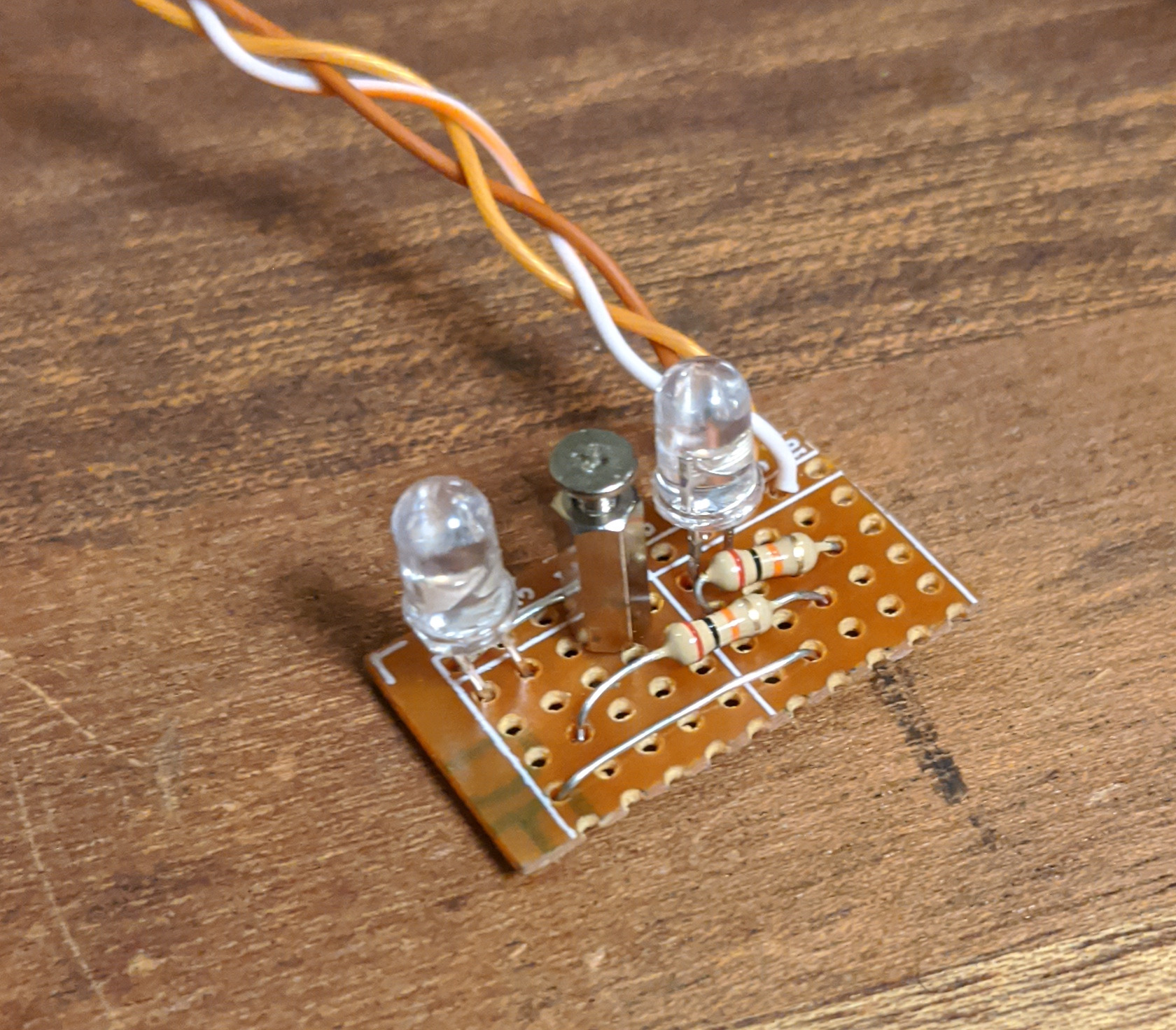
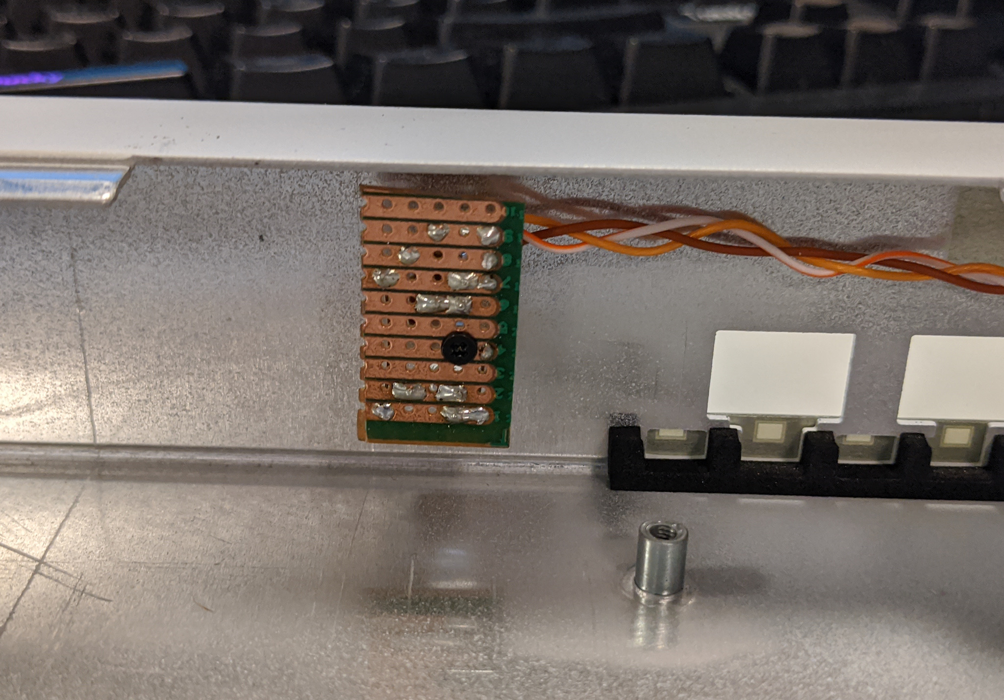
I soldered up this little piece of stripboard with 2 purple LEDs and 20kΩ current-limiting resistors and attached an M2 standoff to it for mounting to the switch.
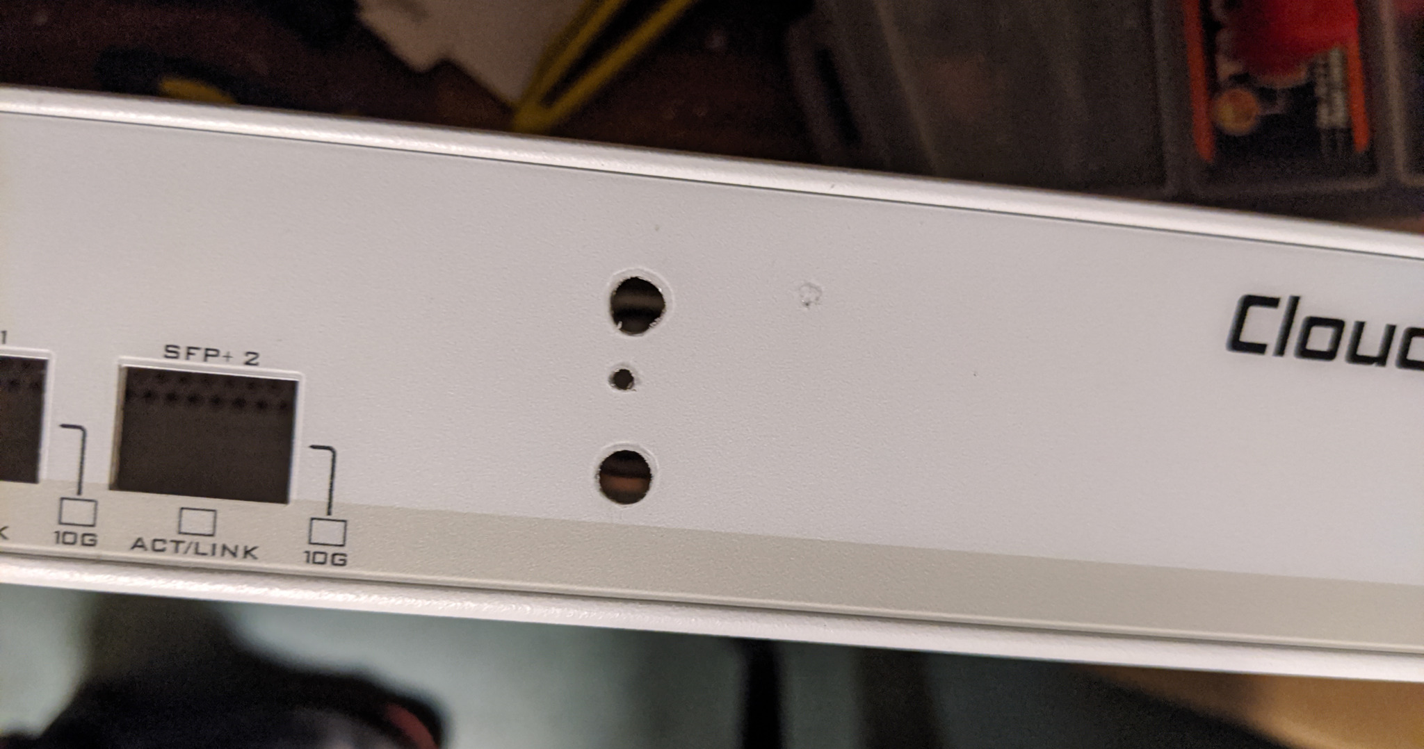
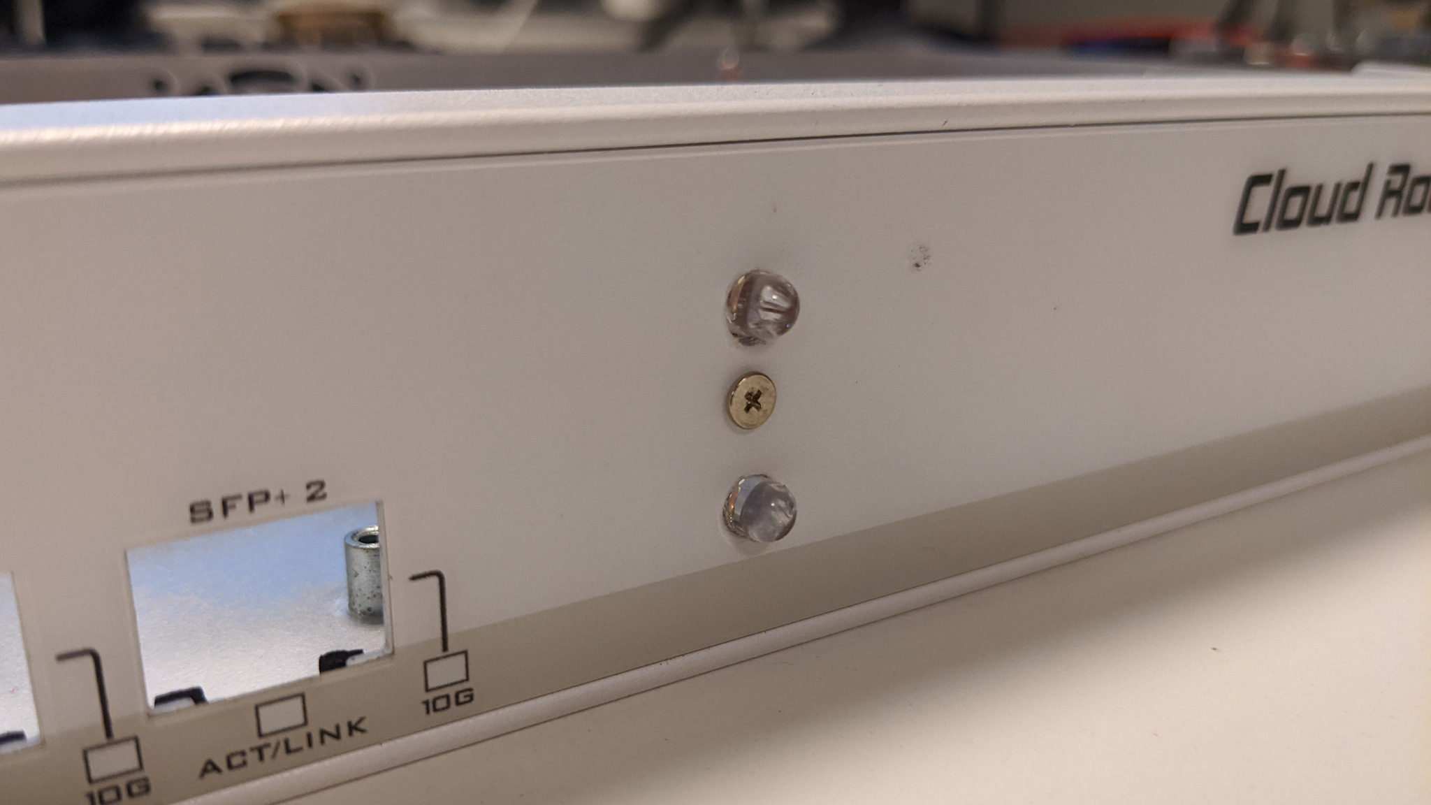
Then I drilled some holes to the front of the switch and screwed it in.
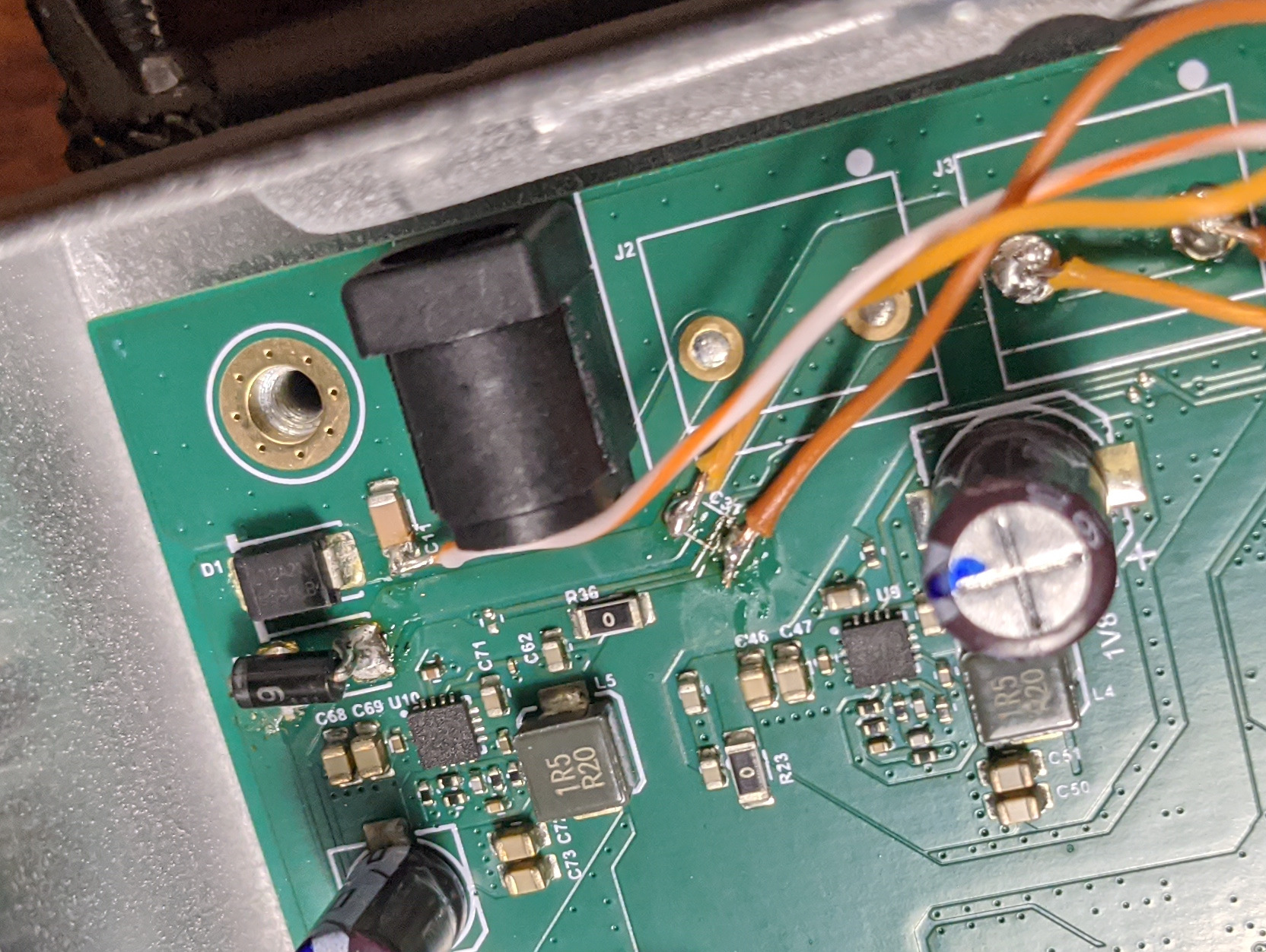
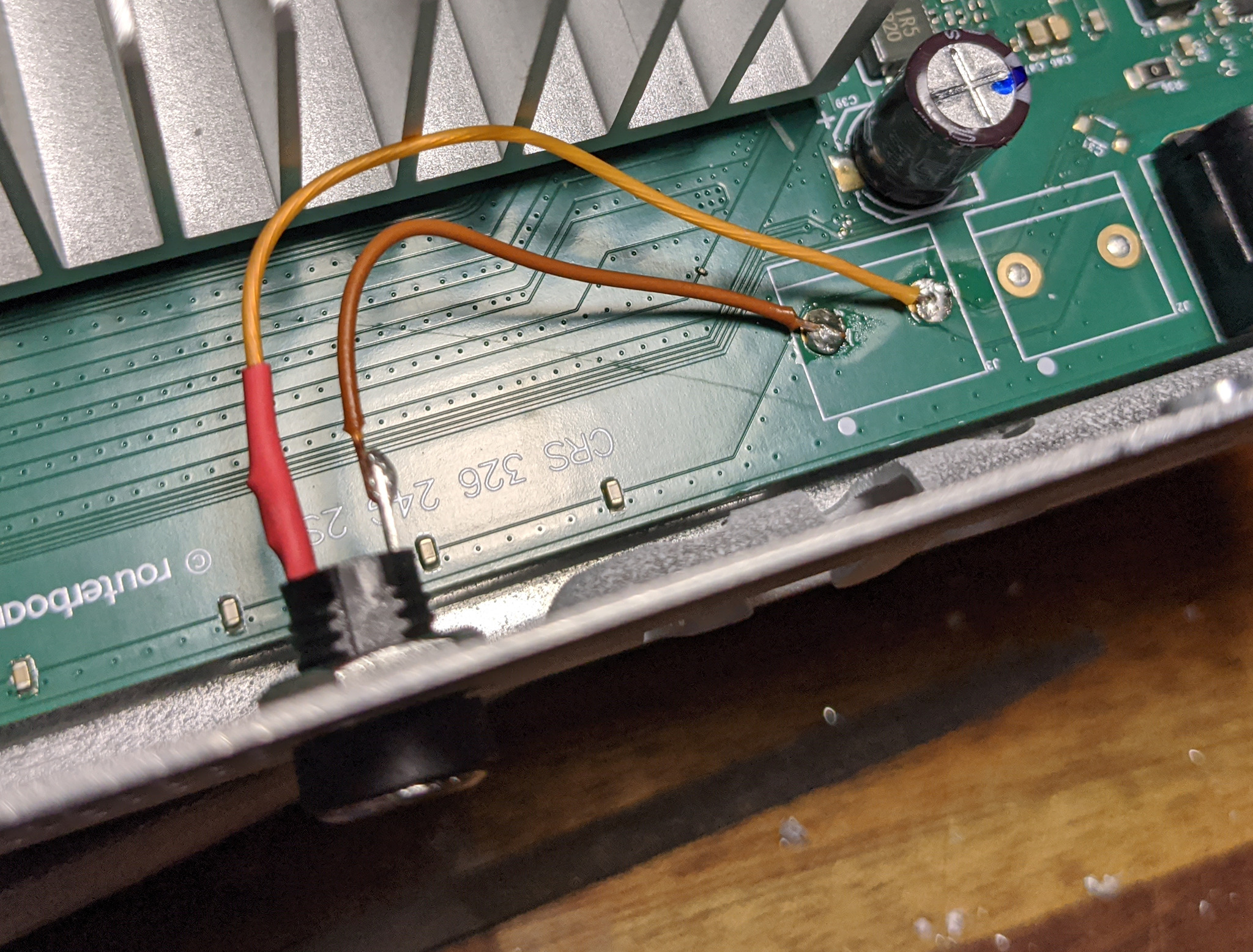
I soldered the LED for PSU 1 to the side of C11, and the ground wire and the LED for PSU 2 to the pads of C31. I didn’t bother soldering a capacitor in C31’s place because it’s not absolutely necessary and I’m lazy.
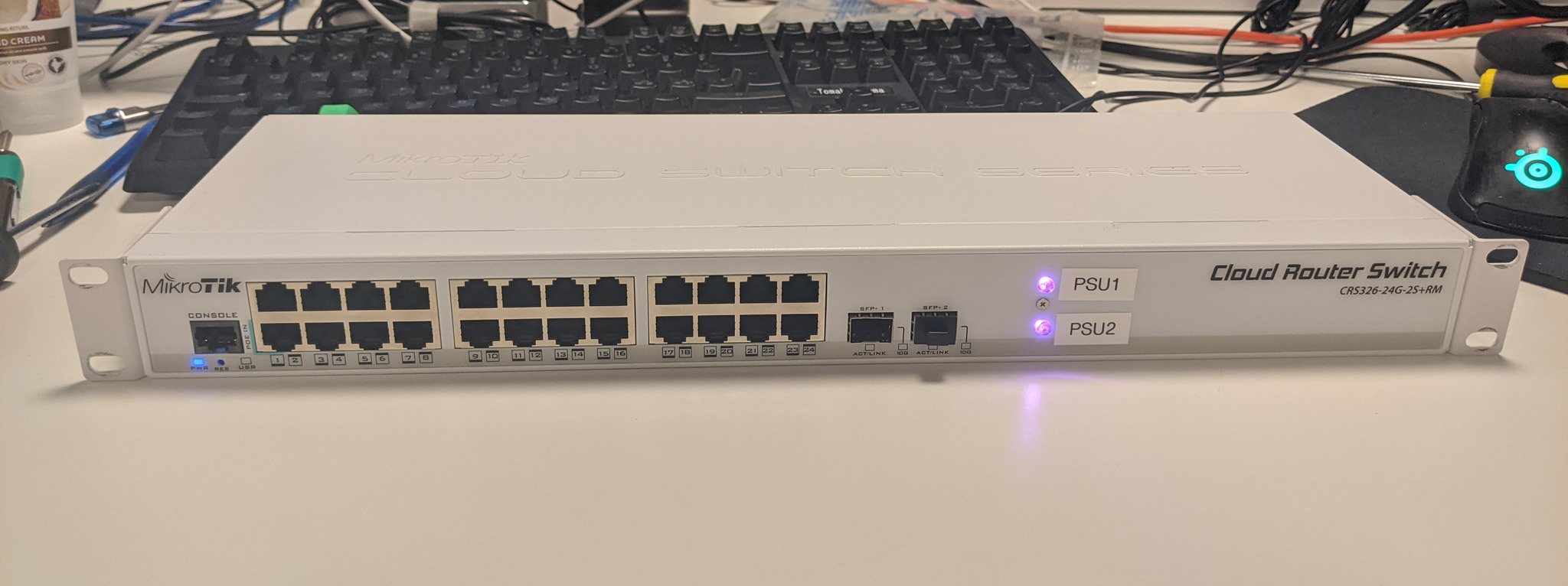
And that’s it. Now we have a switch with redundant power inputs and indicator lights to easily see if both power supplies are plugged in when the switch is mounted in a rack.