Rectifinuverter (WaveWrecker)
-
 Feb 08, 2024
The Rectifinuverter consists of two half-wave rectifiers that can either split a single input signal into a positive and a negative half, or half-wave rectify 2 seperate input signals independently. After being rectified the signals are routed through attenuverters and sent to their outputs, as well as to a third mixed output.
Some ways the module can be used:
- Two independent half-wave rectifiers
- Single full-wave rectifier
- Creating new waveforms by combining the top half of a wave with the bottom half of another.
Backstory
This module isn’t my original creation. Jakob haQ (check out his youtube channel) came up with the original idea and design for a module that splits a wave into its positive and negative half, and posted it on Moritz Klein’s discord community. After I and a couple other people provided feedback on the design, ericboon joined in and made some improvements to the circuit and had the idea of adding attenuverters after the rectifiers. I thought this module turned out to be interesting and wanted to build one so I then started working on a stripboard layout. While working on the layout, I got the idea of adding the mixed output, which would allow the module to also work as a full-wave rectifier. The result is this module. Later ericboon also added an offset control to the circuit but that isn’t included in my version.
Schematic
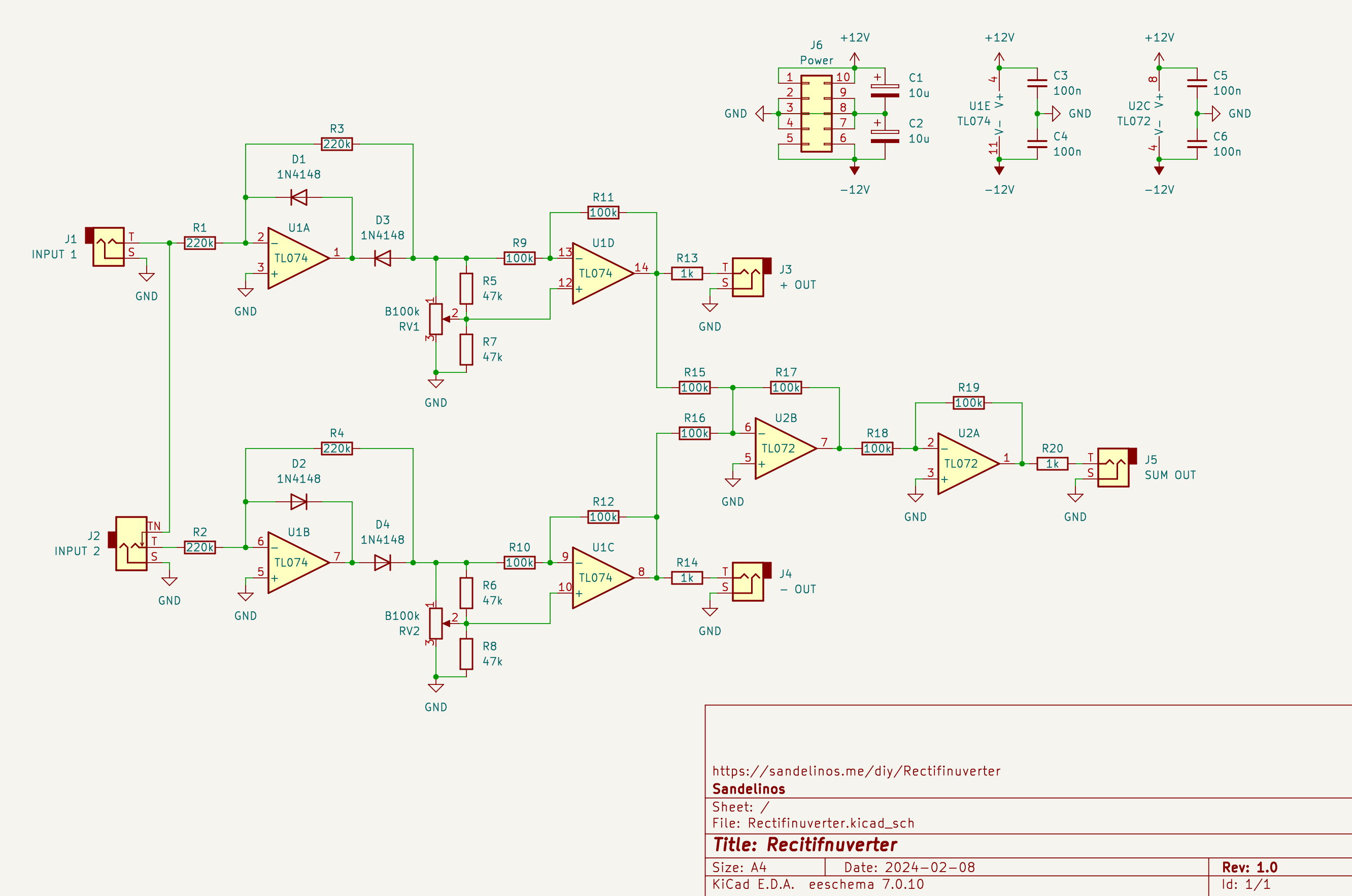
Download:
Stripboard layout
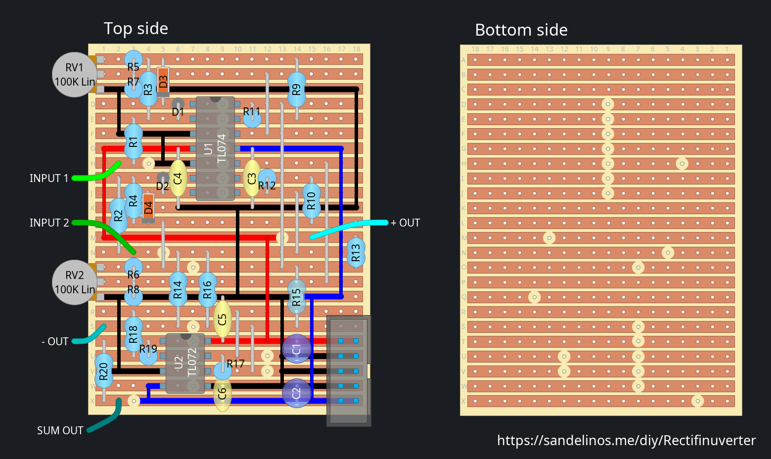
Download: Rectifinuverter-stripboard.diy (0.1 MiB)
BOM
| Name | Value |
|---|---|
| R1, R2, R3, R4 | 220k |
| R5, R6, R7, R8 | 47k |
| R9, R10, R11, R12, R15, R16, R17, R18, R19 | 100k |
| R13, R14, R20 | 1k |
| C1, C2 | 10μ |
| C3, C4, C5, C6 | 100n |
| D1, D2, D3, D4 | 1N4148 |
| U1 | TL074 |
| U2 | TL072 |
Notes
With the values listed here the gain range of the inputs is 1 to -1. If you
want to increase the gain you can replace R3 and R4 with a larger value. I
actually replaced them with 300k in the module I built.
R5, R6, R7 and R8 are used to skew the attenuverter potentiometers'
response curves towards the middle (learn more
here).
If you prefer a linear response you can leave them out. I left them out in my
build.
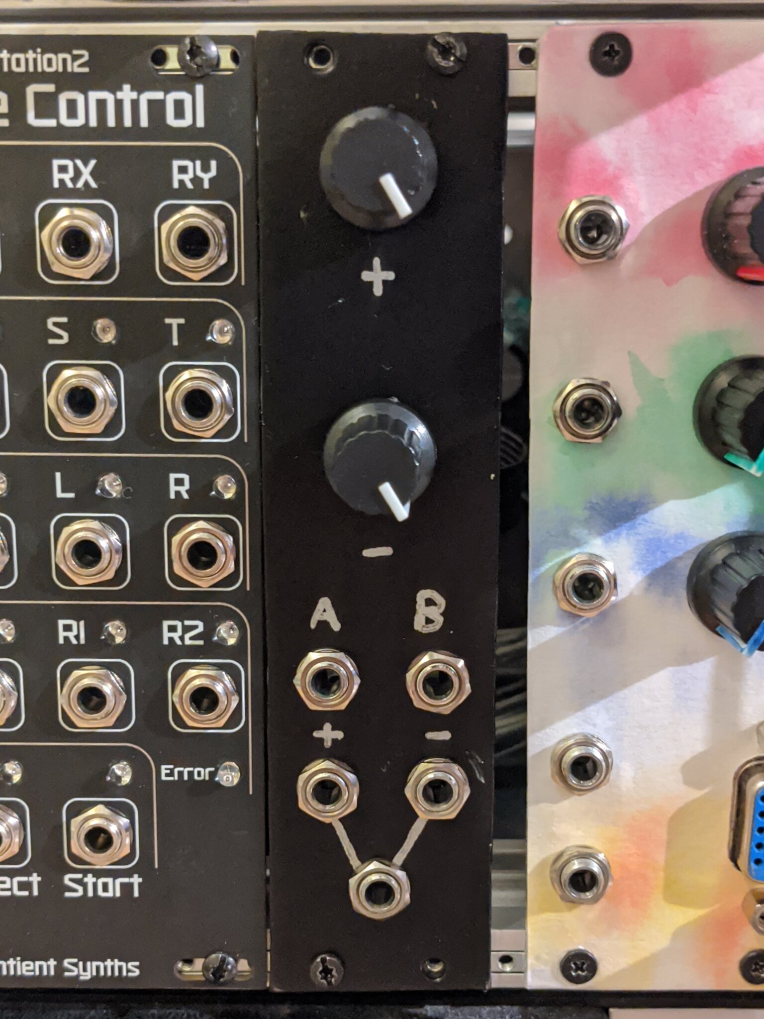
Panel
Here’s the template I used to make the panel:
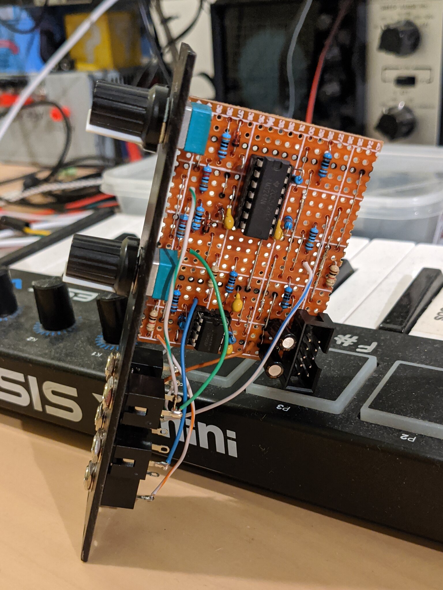
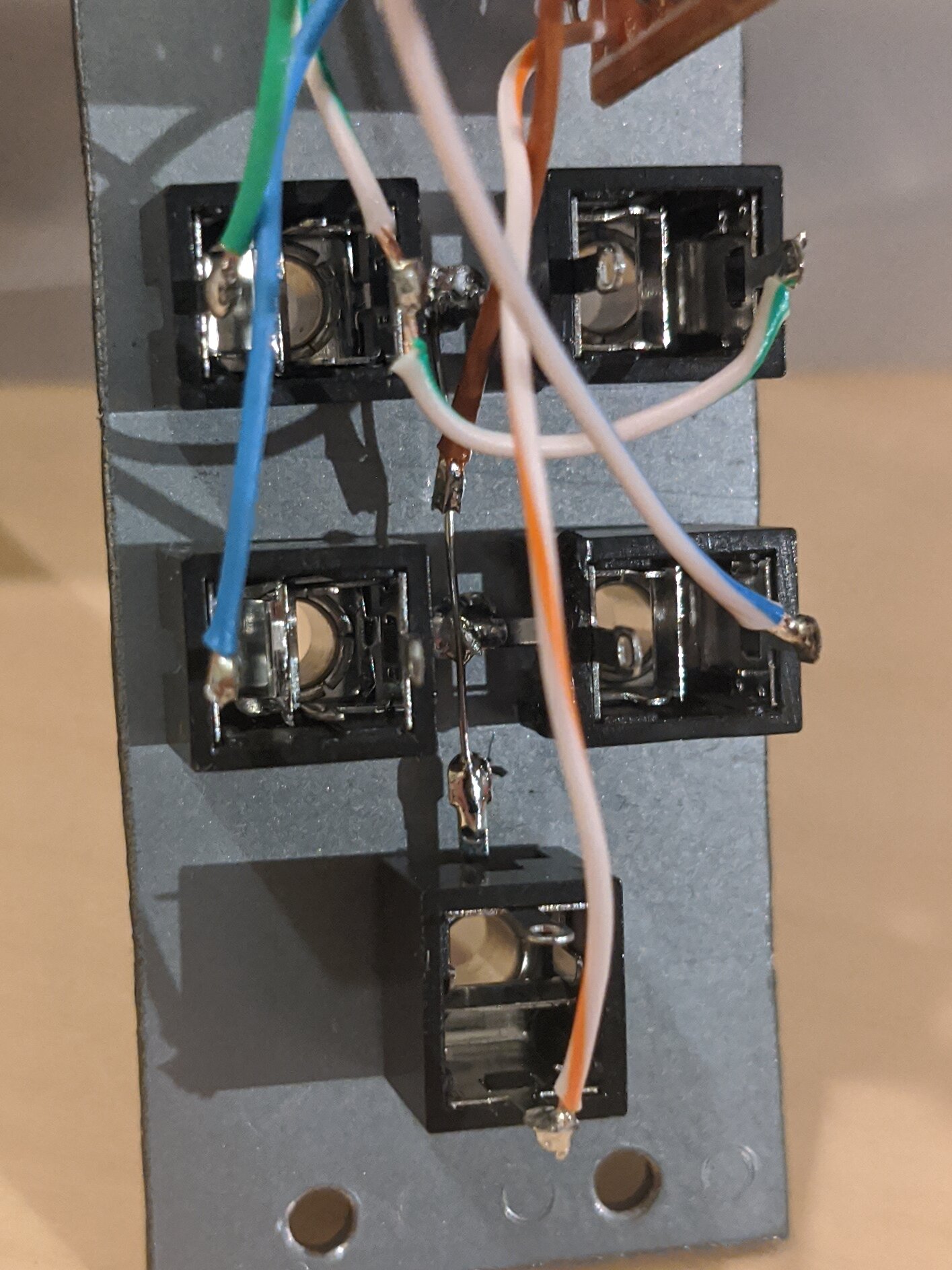
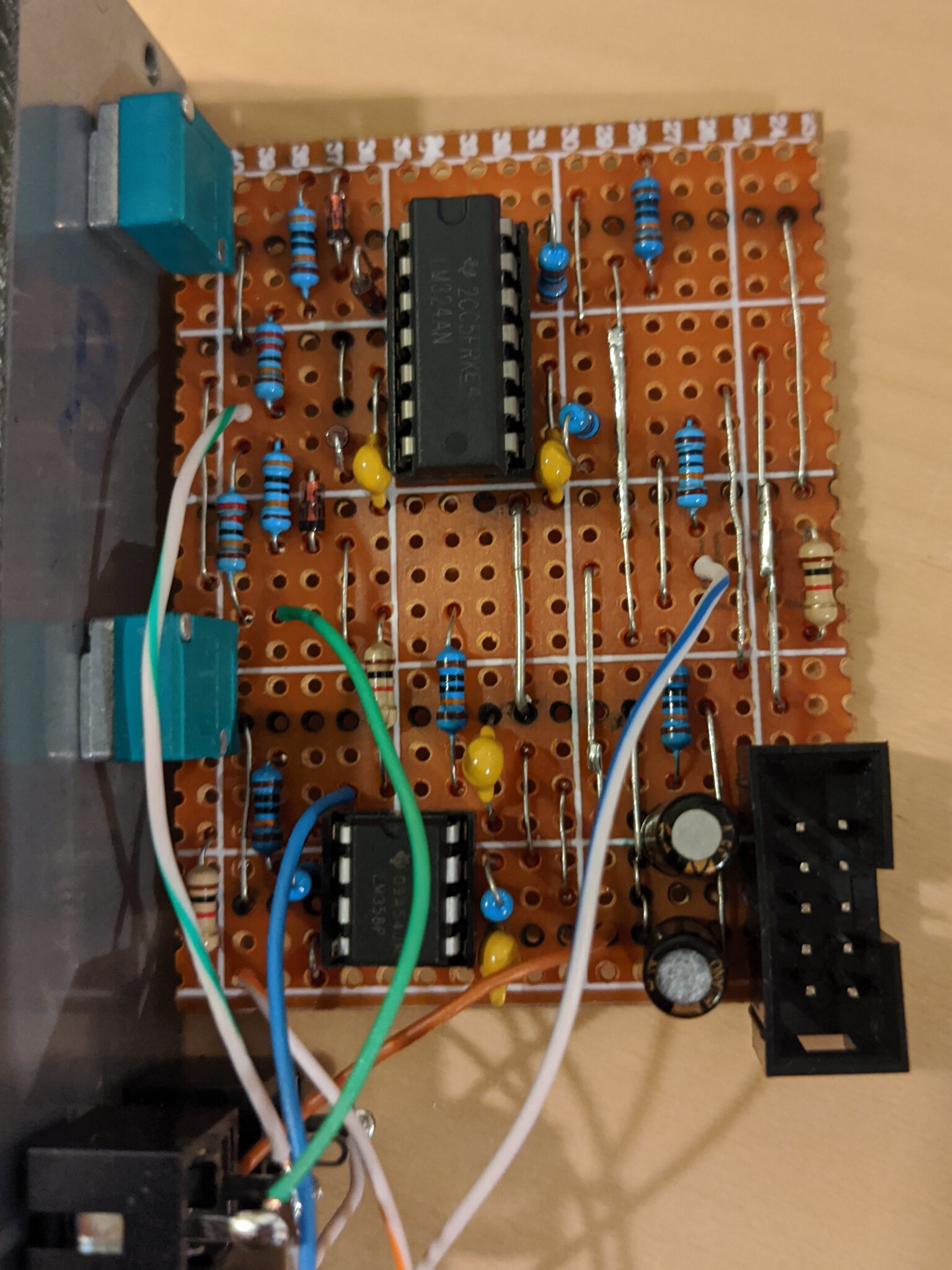
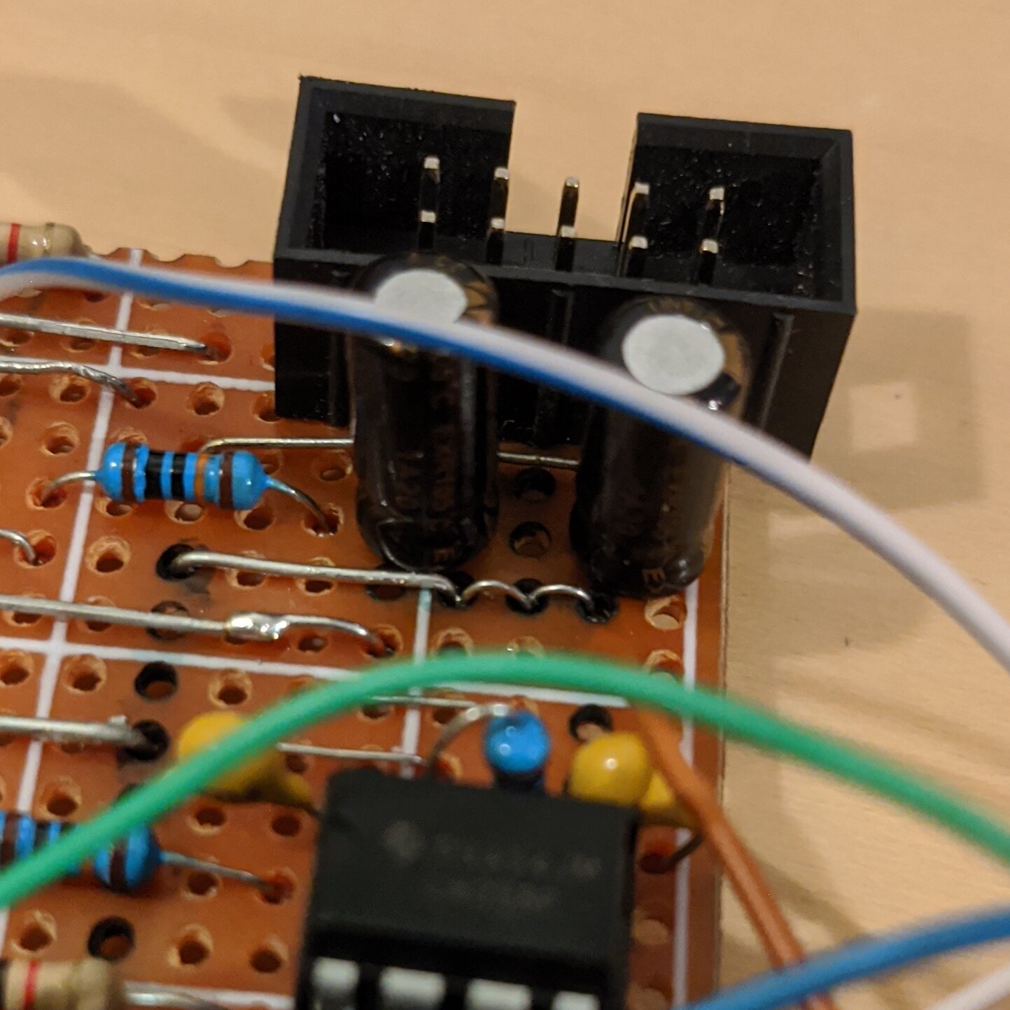
Photos