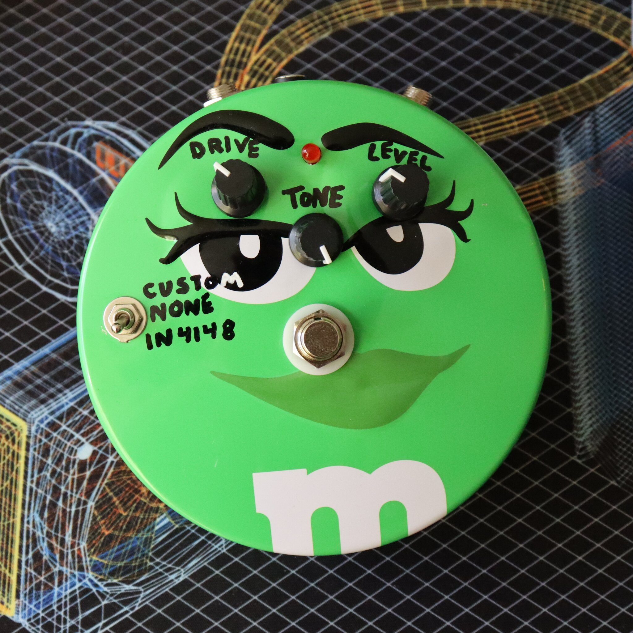
Tube Screamer in a face
-
 Jul 01, 2023
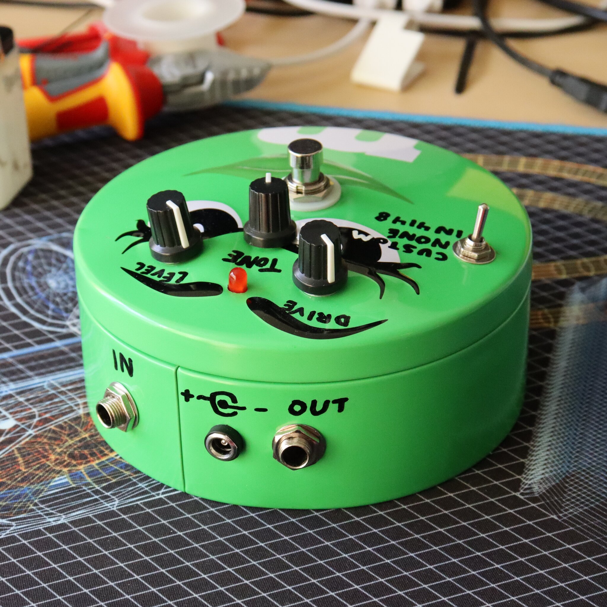
I somehow ended up with another one of these m&m tins. A green one this time so
a tube screamer was an obvious choice for the pedal to build in it. There are
some layouts for the tube screamer around the internet but I decided to make my
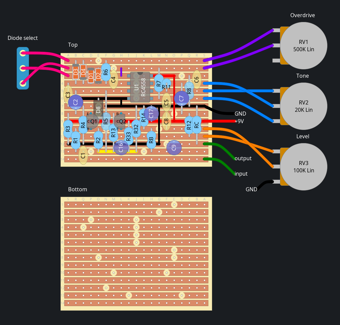
own because it’s more fun. On the first layout I made
I forgot R9, which I only noticed while writing this post so I had to bodge
that on after the fact. This has been fixed in the layout below.
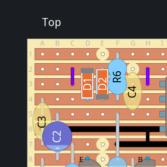
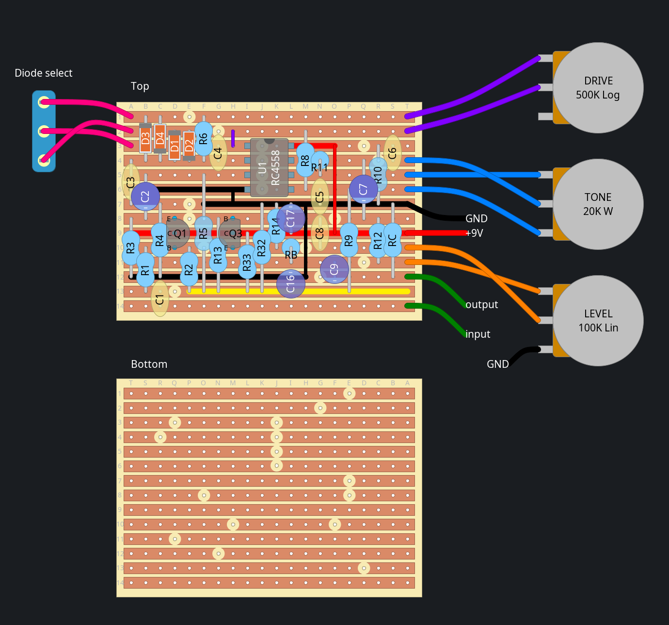
Stripboard layout
BOM
| Part | Original | What I used |
|---|---|---|
| C1 | 20n | 22n |
| C2,C7 | 1μ | |
| C3 | 47n | 68n |
| C4 | 51p | 47p |
| C5,C6 | 220n | 100n+100n=200n |
| C8 | 100n | |
| C9 | 10μ | |
| C16 | 47μ | |
| C17 | 100μ | |
| R1,R7,R11,R12 | 1k | |
| R2,R13 | 510k | 470k |
| R3,R5,R9,R14,R32,R33,RC | 10k | |
| R4 | 4k7 | |
| R6 | 51k | |
| R8 | 220 | |
| RB | 100 | |
| DRIVE | A500k | B1M |
| TONE | W20k | B20k |
| LEVEL | B100k | |
| D1,D2 | MA150 | 1N4148 |
| Q1,Q3 | 2SC1815 | 2SC2240 |
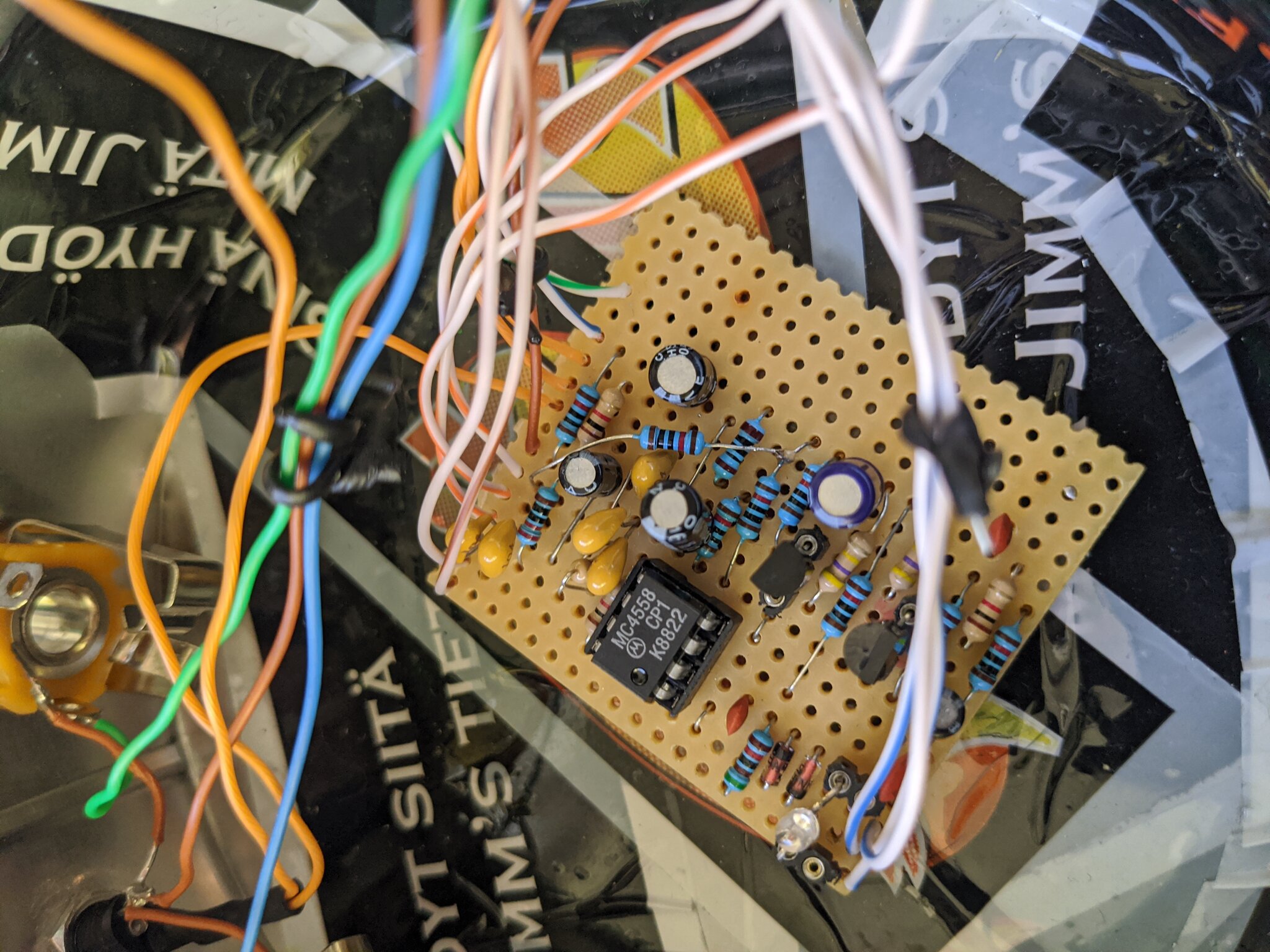
| U1 | JNR4558 | MC4558 |
Schematic
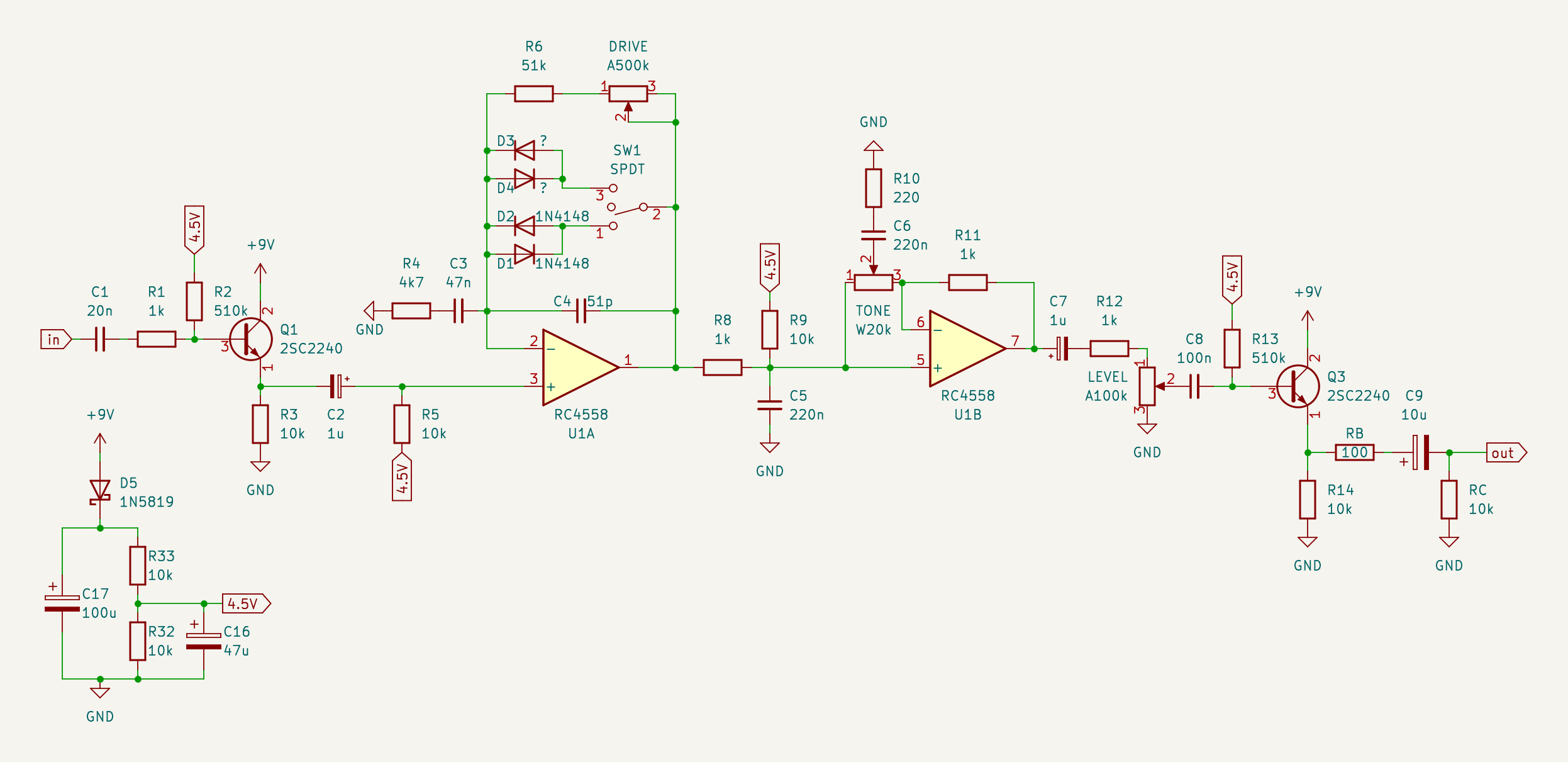
Dowload:
Changes I made
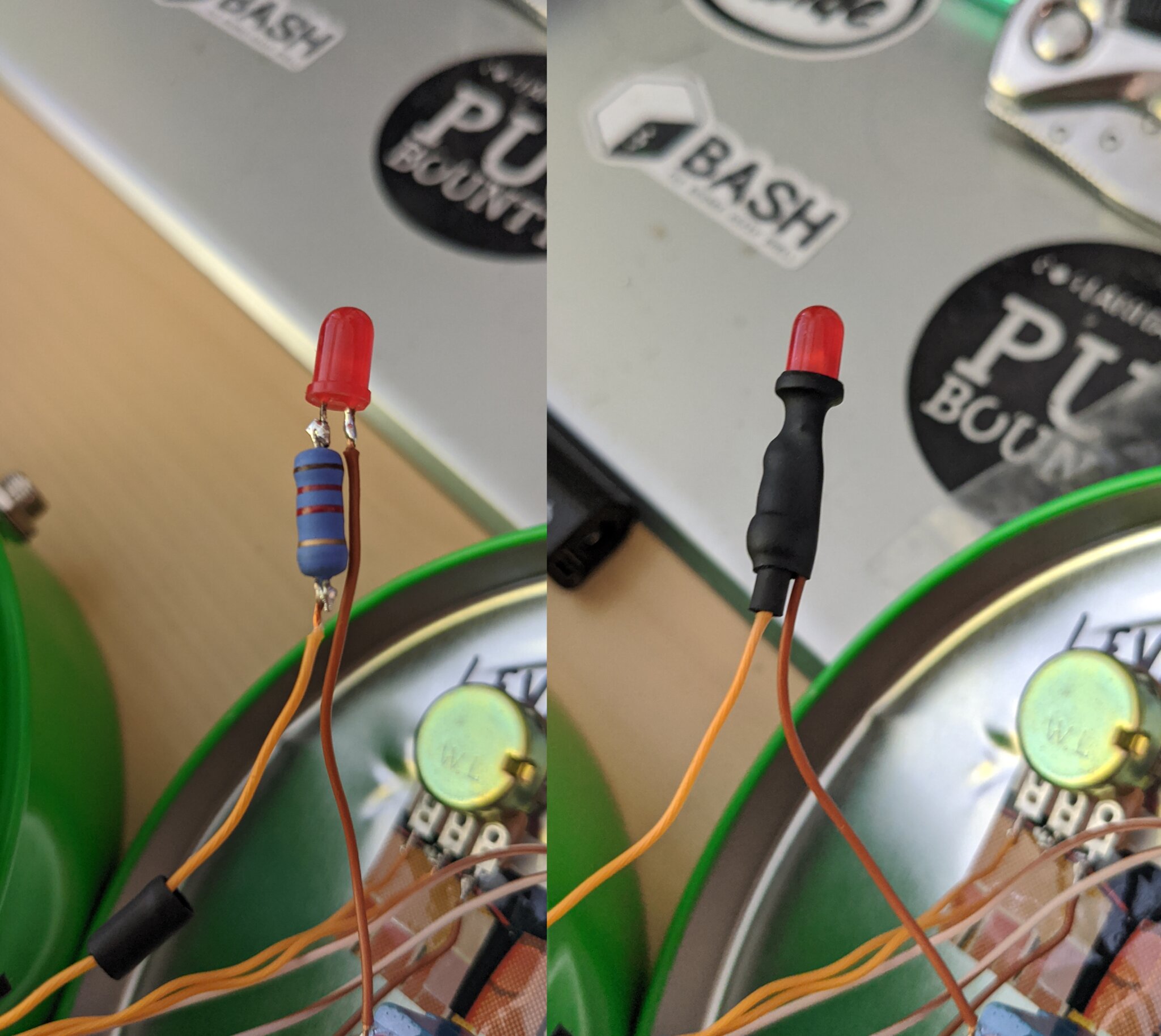
I added a 3-way switch to select between 2 sets of diodes or no diodes at all in the middle position. I soldered on pin sockets for the 2nd set of diodes so I can swap in different ones when I want. Currently I have a single bipolar red/blue led in the socket, which sounds pretty nice to me. If you’re building this and don’t want the diode switch you can get rid of the 2nd pair of diodes and add a jumper like below.
I also got rid of the reverse-polarity protection diode D8 because I’m not a fan of that style of reverse-polarity-protection and instead replaced it with a series diode that I soldered straight to the DC socket.
Component substitutions
I built this out of parts I had lying around so I didn’t have the exact right values for many components. Here is some reasoning for the substitute values I picked. The original values and the values I used are listed in the BOM above.
C3
In the original circuit R4 and C3 form a 720Hz highpass in the clipping
stage. The closest values I had on hand were 22n and 68n, which would’ve ended
up with 1.5kHz and 498Hz cutoffs respectively (I could’ve used 2 22n in
parallel to get 769Hz too). I went with the 68n for a more dark fuzzy tone.
C4
R6, the drive pot and C4 form a low-pass filter in the feedback loop of the
clipping stage. The frequency depends on the position of the drive knob. With
the original component values it goes from 61kHz to 5.7kHz as you turn up the
drive knob. I went with 47p for a 6.1kHz cutoff at max drive. (3kHz with the 1M
drive pot)
C5
In the original circuit R8 and C5 form a 723Hz lowpass filter after
the clipping stage. The closest options I had with the parts I had on hand were
either to use 2 100n caps in parallel to get 200n for a 796Hz cutoff or to use
a 100n and a 150n in parallel to get 250n for a 637Hz cutoff. I preferred to
have the sound be a little bit brighter as opposed to darker so I went with the
200n.
C6
Depending on the position of the tone knob, R8 and C6 form either a lowpass filter or a highpass filter with a cutoff frequency of 3.3kHz. As with C5 I had the choice of either 200n or 250n. With 200n the cutoff frequency of the tone knob would be 3.6kHz or with 250n it would be 2.9kHz. I chose to go with 200n again to go brighter rather than darker. I mostly play the pedal with the tone control turned all the way to the treble side though so maybe it would’ve been a better idea to go for 250n to get a 2.9kHz cutoff to retain a little bit more of the high mids.
C1, R2, R13
These are all part of subsonic highpass filters used for DC biasing. Their exact values don’t change the sound at all as long as you don’t go above 20Hz.
Drive pot
The original circuit has a logarithmic 500k drive pot. I didn’t have any of those on hand so I used a linear 1M pot instead. With the linear taper of my pot it’s harder to dial in low drive settings but I love distortion so it doesn’t matter much to me. Also when I turn the drive pot up past 50% I get even more distortion than the original tube screamer offers, which is nice.
D1, D2
The MA150 is just a generic silicon switching diode. I used 1N4148 because
those are what I have a bunch of.
Q1, Q3
These are just used as buffers and don’t effect the sound of the pedal.
Normally I’d use 2N3904 since that’s my general-purpose NPN of choice but I
happen to have a bag of 2SC2240 lying around so I went with them since they
have the same pinout as the original 2SC1815. (Which makes this a bit harder
for you to build unless you also have some NPNs with a E-C-B pinout lying
around. Sorry. ☹️)
U1
Since there is no opamp-clipping happening in the circuit (unless you turn the
diode switch to the middle position) the choice of opamp doesn’t really matter.
I think I originally used a LM358 but I swapped in a “vintage” Motorola
MC4558 I found in my bag of chips salvaged from broken electronics just
because why not.
Pictures
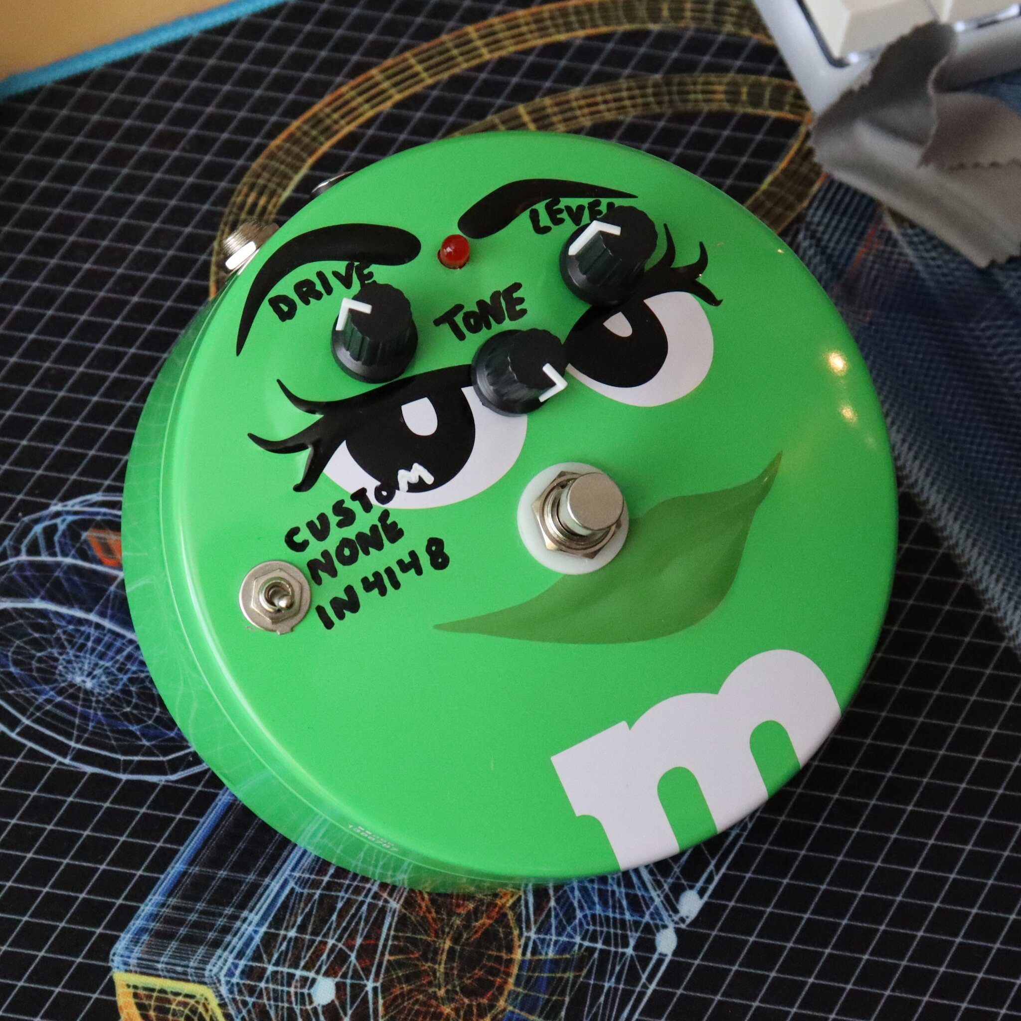
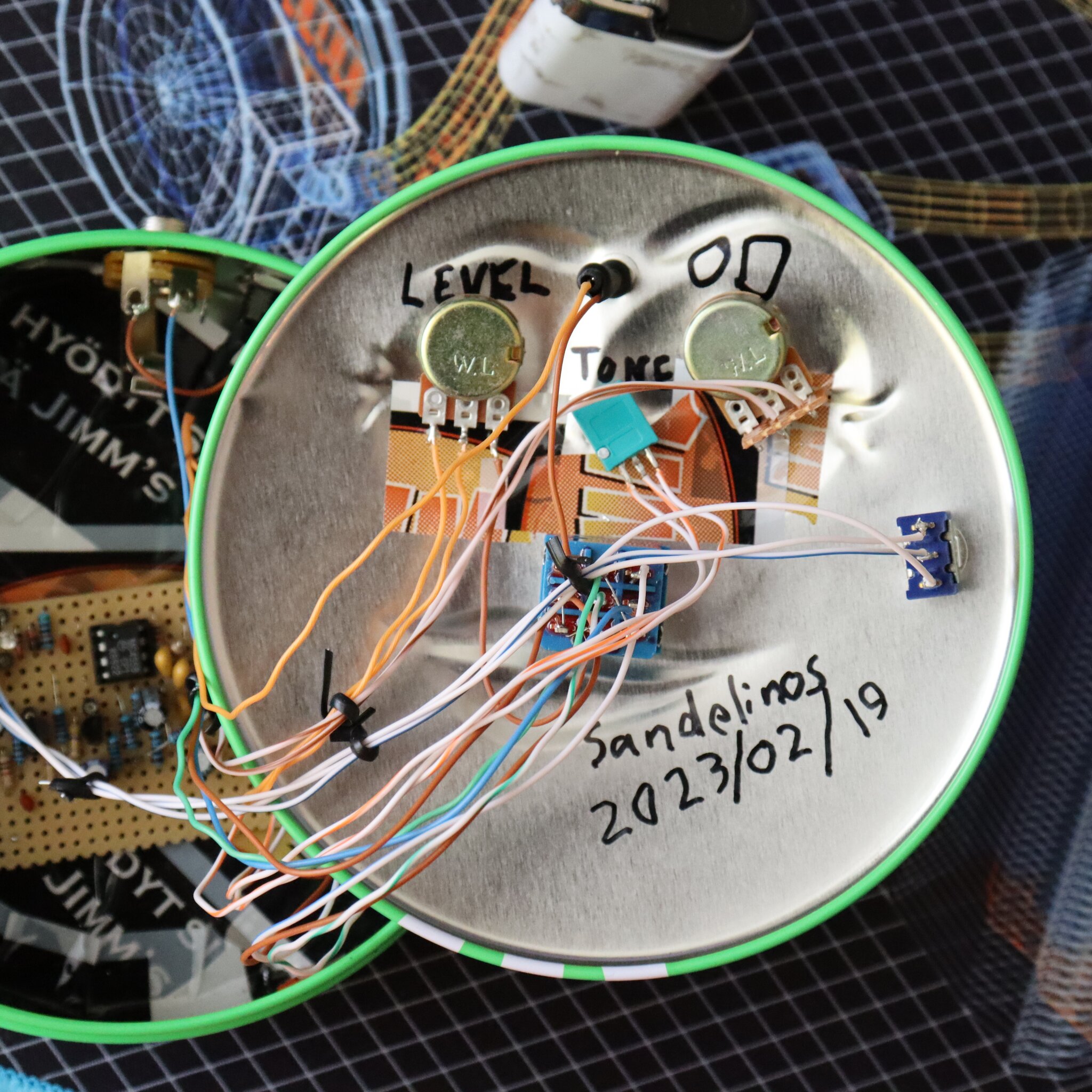
(Tucker, if you’re reading this I’m sorry but you can’t have it.)